Search This Blog

Powered by Blogger.

Translate

There's a 'Desert' in The Middle of The Pacific. Here's What Lives There

In the centre of the South Pacific, there's a place as far away from land as anyone on Earth could ever hope to get. The ocean is different there.

These distant waters lie at the heart of the South Pacific Gyre, the centre of which holds the 'oceanic pole of inaccessibility': the ocean's remotest extreme, aka Point Nemo (a name meaning 'no-one'), famous otherwise for being a spacecraft cemetery.

But aside from the ghosts of burnt-up satellites, what dwells under these far-off waves?

Not much, scientists have long thought. Despite taking up 10 percent of the ocean's surface, the South Pacific Gyre (SPG) – the largest of Earth's five giant ocean-spanning current systems – is generally considered a 'desert' in terms of marine biology.

Nonetheless, stuff does live there, even if organic life in these waters (and the seabed below it) is few and far between, due to a range of factors.

These include distance from land (and the nutrient matter it provides), the way water swirling currents isolate the centre of the gyre from the rest of the ocean, and high UV levels in this part of the ocean.

In truth, though, we don't actually know all that much about the life-forms that inhabit the SPG, largely because of how hard it is to study this oceanic desert – due to both its extreme remoteness, and also how large it is, covering about 37 million square kilometres (14 million square miles).

Despite the challenges, a recent international research effort has given us what the scientists claim is an unparalleled glimpse at the microbial creatures that exist in these waters.

During a six-week expedition aboard the German research vessel FS Sonne from December 2015 to January 2016, a crew led by the Max Planck Institute for Marine Microbiology sailed a 7,000-kilometre (4,350 miles) journey through the SPG from Chile to New Zealand.

En route, they sampled the microbial populations of the remote waters at depths between 20 to 5,000 metres (65 ft to 16,400 ft), using a newly developed analysis system that enabled the researchers to sequence and identify organic samples en route in as little as 35 hours.
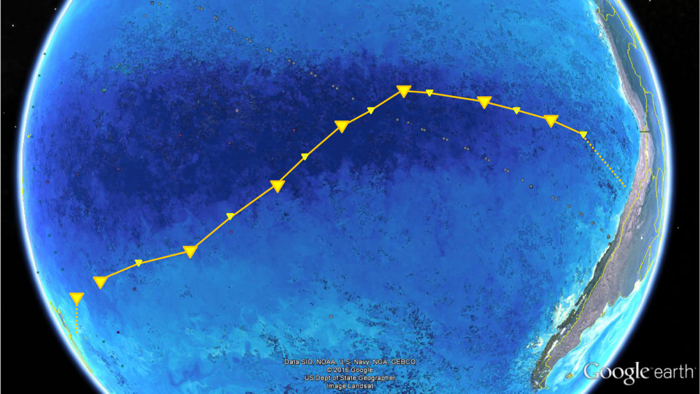
016 south pacific gyre 1 (Max Planck Institute for Marine Microbiology/Google Earth/NASA)

Above: FS Sonne's path crossing the SPG from Chile to New Zealand.

"To our surprise, we found about a third less cells in South Pacific surface waters compared to ocean gyres in the Atlantic", said one of the researchers, microbial ecologist Bernhard Fuchs, back in July 2019.

"It was probably the lowest cell numbers ever measured in oceanic surface waters."

Among the microbes the team found, 20 major bacterial clades dominated the lot. These were mostly organisms scientists have encountered in other gyre systems, such as SAR11, SAR116, SAR86, Prochlorococcus, and more.

The distribution of these microbe communities depended largely on water depth, based around factors such as changes in temperature, nutrient concentrations, and availability of light.

One of the populations identified, called AEGEAN–169, was particularly numerous in the surface waters of the SPG, whereas previous research had only discovered them at 500-metre depths.

"This indicates an interesting potential adaptation to ultraoligotrophic [low in biological productivity] waters and high solar irradiance", said one of the team, microbiologist Greta Reintjes.

"It is definitely something we will investigate further."

On the whole though, the sampling generally confirmed that the SPG is a "unique, ultraoligotrophic habitat", where low nutrient availability restricts growth to specialist oligotrophic organisms and creatures that have adapted to "extreme physicochemical conditions".

In other words, the SPG can't shake off its 'desert' reputation just yet, but there is a bright side to all that organic absence: these distant, almost lifeless waters are said to be the clearest ocean in all the world.

The findings were reported in Environmental Microbiology.

A version of this article was first published in July 2019.


Source: https://www.sciencealert.com

[TC] Ultrasonic Proximity Detector

This ultrasonic proximity detector comprising independent, battery-powered transmitter and receiver sections makes use of a pair of matched ultrasonic piezoceramic transducers operating at around 40 kHz each. This circuit can be used in exhibitions to switch on prerecorded audio/video messages automatically when a visitor evincing interest in a product comes near an exhibited product.

Fig. 1: Transmitter circuit
Fig. 1 shows the transmitter circuit. It comprises CMOS timer IC 7555 (IC1) configured as an astable multivibrator, which may be tuned to the frequency of the ultrasonic piezoceramic transmitter’s resonant frequency of around 40 kHz using preset VR1. A complementary pair of transistors T1 and T2 is used for driving and buffering the transducer while it draws spikes of current from IC1 circuit to sustain oscillations and thereby avoids any damage.

The receiver front-end (refer Fig. 2) is designed to provide a very high gain for the reflected faint ultrasonic frequency signals detected by the ultrasonic transducer. The amplifiers built around N1 and N2, respectively, provide AC voltage gain of around 80 each. These two stages should have a high open-circuit gain, wide bandwidth and very low bias current apart from being capable of single-supply operation. Quad op-amp LM324 is used here due to its low cost. For higher efficiency, you may use single op-amps such as CA3130 or CA3140.

Fig. 2: Receiver circuit


Fig. 3: Pinconfigurations oftransistors BC327and BC337
When a visitor pauses before a sistor R10 is used to meet this requirement. The filter also helps to bypass brief bursts of ambient noise in the ultrasonic range. The third stage comprising N3 works as a comparator to provide a triggering pulse when a visitor stops by. This pulse can be used to trigger a timer or a monostable, whose output may then be used to switch on the audio/video message concerning the product for a predetermined period.

When somebody comes in front of the ultrasonic piezoceramic transducer pair, the status LED (LED1) glows because of the signal reflected from the body of the visitor.

The circuit can be assembled on any general-purpose PCB. The transmitter and the receiver should be aligned such that the transmitted ultrasonic signal is optimally received by the receiver after reflection. Fig. 3 shows the pin configuration of transistors T1 and T2, while Fig. 4 shows installation of the ultrasonic piezoceramic transducer pair operating at around 40 kHz.


Source: http://electronicsforu.com/
 

Fig. 4: Installation of transducer pair

IC based TV transmitter circuit


TV transmitter circuit.

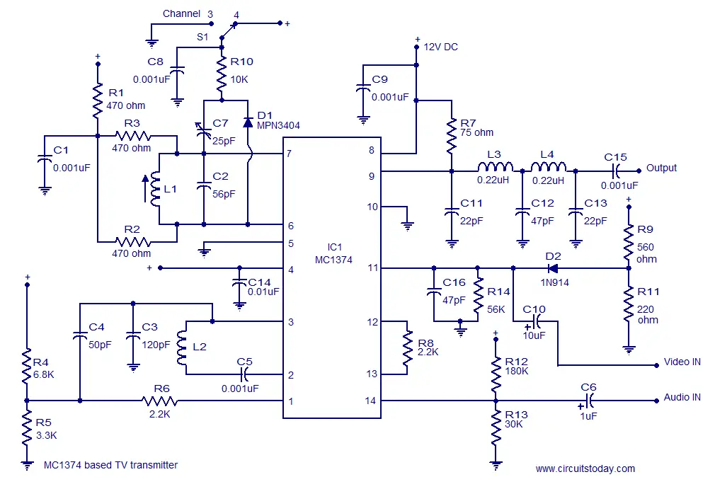
A very simple and high quality TV transmitter circuit based on IC MC374 is shown in this article.MC1374 is an integrated TV modulator circuit that can be used in various TV transmitter applications. The MC1374 includes all necessary circuitries required for a TV modulator such as sound carrier oscillator, FM audio modulator, dual input RF modulator etc. The IC packed with a lot of great features like wide dynamic range, single supply operation, low distortion, variable gain radio frequency modulator section, minimum intermodulation distortion, + or – Sync etc. The IC requires few external components and can be operated from a supply voltage range from 5 to 12V DC.The circuit diagram of the TV transmitter using MC1374 is shown below.

TV modulator circuit
MC1374 TV transmitter circuit

Circuit description.

Video section.

The video signal input to the circuit can be either negative or positive. The RF output will be approximately zero when the voltages at pin 1 and 11 are equal and the RF output increases linearly as the difference in voltage increases. Resistors R1,R2 and R3 determines the Q factor of the circuit are here their values are so chosen that the Q factor is around 15 which is the desired value for this IC. Resistor R8 connected between pins 12 and 13 sets the modulator gain. The RF output is available from pin 9 which is actually a source which drives a load connected from positive supply line to pin 9. The frequency of the RF oscillator is controlled by the tank circuit comprising of components L1 and C2 connected in association with pins 7 and 6. With the present values of L1 and C2 the RF oscillator frequency is around 105MHz. Components L3, L4, C11, C12 and C13 forms a double pi low pass filter which filters away second harmonics from the radio frequency output. These second harmonics usually occur at very high frequencies due to small imbalances in the device. Resistors R9 and R11 forms the bias circuit for the video input pin. Switch S1 can be used for selecting channel 3 or channel 4 operations.

Audio section.

Frequency modulation is used for transmitting the audio signals. Inductor L2 connected between pin 2 & 3 and the capacitor C3 from pin 3 to ground forms the necessary tank circuit for the FM sections oscillator. Resistor R12 and R13 forms a biasing network for the audio input pin (pin14). C6 is the decoupling capacitor for the audio input while C10 is the decoupling capacitor for the video input. The modulate FM signal available at pin 3 of the IC is coupled pin 1 of the IC through resistor R6 and capacitor C4 and then this signal is modulated onto the AM carrier. Capacitor C9 filters off noise if any from the power supply. R4 and R5 form a biasing network for the pin 1 of the IC. C14 a noise bypass capacitor for the oscillator B+ pin (pin14) of the IC. This pin can be used for shutting down the sound system during the alignment of the AM section.

Notes.

  • Assemble the circuit on a good quality PCB.
  • Use a holder for mounting the IC.
  • Circuit can be powered from anything between 5 to 12V DC.
  • Using a battery for powering the circuit will reduce noise and improve the performance.
  • If a DC power supply is used, then it must be well regulated.
  • For L1 make 4 turns of #22 enamelled copper wire on a 0.25 inch plastic former.
  • For L2 make 40 turns of #36 enamelled copper wire on a 0.18 inch plastic former

Page Rank

google pagerank

Write For Us

Submit a Guest Post

Find us on Facebook

Categories

555 Timer IC 7 segment Display 8051 Project AC Circuits Adafruit Alarms Amplifier Circuits Analog Circuits android Arduino arm processor Assembly Languange Atmel Atom Size Audio Circuits augmented reality Automotive Circuits avr Battery Circuits Bicycle Gurad bluetooth Cable TV Circuits Cambridge University Camera Technology Circuit Boards Clipping And Clamping Circuits Clocking And Timer Circuits Computing contact lens Contact Us Form Contests Controller Circuit Conversion Circuits Counter Circuits Digital Electronics diy circuits Downloads EFY EFYTimes Electronic Books Electronic Components Electronic Locks And Keys Engineering Fan Circuits Filter Circuits Fire Alarm free Frequency Fun And Game Circuits future Google Hack n Mod Ham Radio Circuits heart rate monitoring High Voltage Circuits Home Circuits IC Guide ieee Industrial Circuits Infrared Instructables Inventions ipad lcd Led Circuits Light Related Lighting Circuits Medical Circuits Meter Clocks Microcontrollers Microprocessors Mini Projects modules Movie maker NatGeo Navigation Notice Optical Fiber PC Circuits PCB Boards Physics pnp transistor Power Supplies Printing Projects Programmer Project Ideas Projectors Protection circuits Proximity Detectors Radar Radio Circuits Radio Transmitters Raspberry Raspberry Pie Remote Circuits Retis Lab RFID Robot Cars Robotics Science Science Alert Security And Safety Sensor Circuits Servo Motors Smallest Smartwatches sms Software solar cell sound application Spectram Switch Technology News Telephone Related Television Related Test And Measurement Circuits Thermal Projects Tone generator circuits Touch Screen Tutorials Wearables Wi-Fi Wireless
Like us on Facebook
Follow us on Twitter
Recommend us on Google Plus
Subscribe me on RSS