Posted by Jayesh Yewale
Posted on 9:42:00 PM
with No comments
Description.
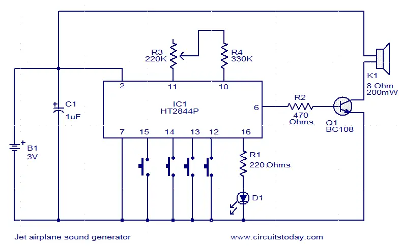
This jet engine sound generator circuit is based on the sound generator IC HT2844P from Holtek Semiconductors. This particular IC can make four sounds namely low speed sound of jet engine, high speed sound of jet engine, missile sound and machine gun sound. Each of these sounds can be activated by connecting the pins 12, 13, 14and 15 to ground by using the respective push button switches. Resistor R3 can be used for manually increasing or decreasing the speed.LED D1 gives a visible indication of the sound.
Posted by Jayesh Yewale
Posted on 11:58:00 PM
with No comments
People have been asking me about interesting applications for the Raspberry Pi, and whether Raspberry Pi is an Arduino killer of some sort. The answer to the second question is no; in fact it is an Arduino augmenter. This blog post answers the first question with another question: how about a Haunted House sound effects machine?
A new revision of the Early Release of Getting Started with Raspberry Pi came out last Friday. I read Matt Richardson’s chapter on using Pygame with the GPIO pins on the Pi, which included a simple Sound Sample player. I adapted his example to work with an Arduino that talks to the Pi over a serial connection; this skeletal (ahem) hookup could easily be incorporated into some sort of Halloween installation. I decided to use Arduino for reading the inputs because out of the box it is more robust and can handle a wider variety of inputs. Also, there are many existing Haunted House triggering demos out in the wild that use Arduino.
First, you’ll need to prepare the trigger circuit. The following example uses three toggle switches, but you can replace those with any kind of on/off input. In a haunted house (or porch-based trick-or-treater installation), a PIR sensor would be handy for triggering based on proximity.
Here’s the basic schematic:
The 10k resistors can be replaced by the Arduino’s own internal pull-up resistors, if you know how to do that.
I connected the Arduino to the Raspberry Pi using a USB cable. While I had the Pi hooked into a monitor, I found that I could just plug the Arduino through my Mac keyboard USB connector and it got enough power from that to work. If you have an older Raspberry Pi with polyfuses limiting the power on the USB port (check to see if you have 2 little green fuses marked “1104″ next to the USB ports), you may need an external hub, or run the Pi headless to free up a USB port.
Next, upload the following sketch to the Arduino:
// PiTalk.ino// Reads three digital inputs. These could be any kind of // switch or (for Halloween) PIR sensors.byte onState[3] = { 0, 0, 0 }; // save the state of each pinvoid setup() { Serial.begin(9600); // Open serial connection pinMode(2, INPUT); // Set these three pins for reading pinMode(3, INPUT); // Each have a 10k pullup externally pinMode(4, INPUT); // so a trigger is LOW}void loop() { for (int i=0; i<3; i++) { // Iterate over pins if (digitalRead(i+2) == LOW) { // Check if triggered if (onState[i] == 0) { // Just triggered? Serial.write(i+2); // Send the pin number onState[i] = 1; // but just once } } else { onState[i] = 0; // Not triggered } } delay(20);}You can use your computer to do upload the program, or you can download and install the Arduino IDE directly on the Raspberry Pi (as described in the next release of Getting Started with Raspberry Pi).Once the Arduino is programmed, open up the Leafpad text editor on the Raspberry Pi and enter this Python program, adapted from Matt’s Sound Sample Player:# playSounds.pyimport pygame.mixerfrom time import sleepfrom sys import exitimport serialpygame.mixer.init(44000, -16, 1, 1024) soundA = pygame.mixer.Sound("Scream.wav") soundB = pygame.mixer.Sound("WilhelmScream.wav")soundC = pygame.mixer.Sound("CastleThunder.wav")soundChannelA = pygame.mixer.Channel(1) soundChannelB = pygame.mixer.Channel(2)soundChannelC = pygame.mixer.Channel(3)print "Sampler Ready."serialFromArduino = serial.Serial("/dev/ttyACM0",9600)serialFromArduino.flush()while True: try: val = ord(serialFromArduino.read()) print(val) if (val == 2): soundChannelA.play(soundA) if (val == 3): soundChannelB.play(soundB) if (val == 4): soundChannelC.play(soundC) val = 0 sleep(.01) except KeyboardInterrupt: exit()
Save it as playSounds.py. Before you run the script you’ll probably need to install the Python serial module. To do that, type:
sudo apt-get install python-serial
If you’re running the latest Raspbian, you probably have everything you need to get this running. Open the LXTerminal and type:
python playSounds.py
If you get an error that Pygame is not installed, type:
When you press the buttons each sound will play once; Pygame’s mixer will even play all three at the same time if you have multiple trick-or-treaters invading your porch
Posted by Jayesh Yewale
Posted on 9:15:00 PM
with No comments
LM3900 multi-channel audio mixer.
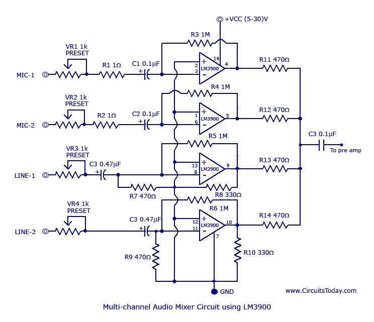
A simple multi-channel audio mixer circuit using LM3900 quad amplifier is given below. The circuit consists of 4 channel quad amplifier (LM3900). Two mic audio inputs and two direct line inputs are available in this circuit. By adding the same circuit parallel with this, you can increase the number of inputs according to the applications. Each input is connected to the inverting terminal of LM3900.The built in amplifier of each section amplifies every audio input separately and is fed to the output terminals. The output terminal from each channel is connected to a single output line with a resistance not greater than 680K and produces a mixed audio at the output with very low noise. This audio mixer circuit doesn’t use a low impedance input to mix ideal sources. Capacitors C1 to C4 are the decoupling capacitors for the corresponding channels. C5 is the output decoupling capacitor.
Circuit Diagram.
Multi channel audio mixer circuit
General Description of LM3900.
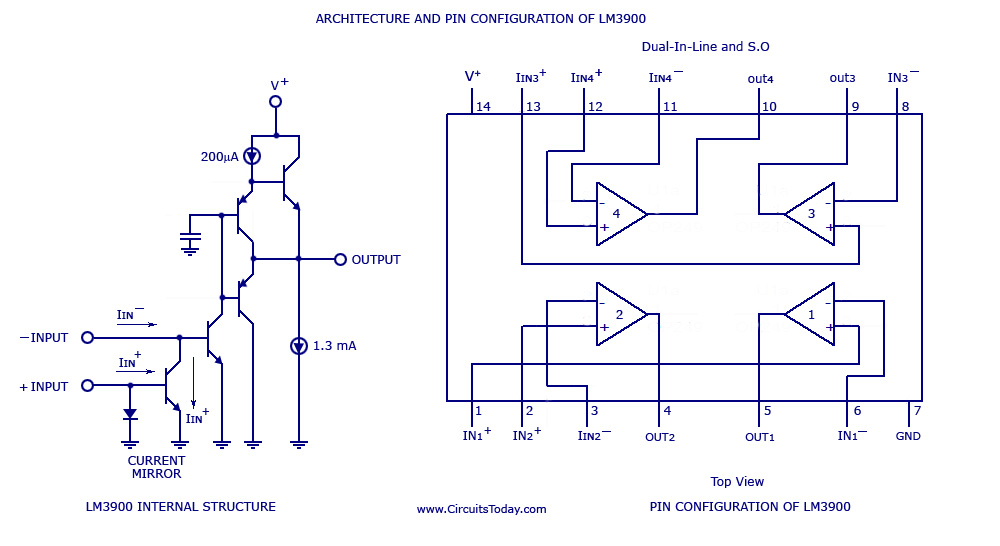
LM3900 series amplifiers consist of four independent and internally compensated amplifiers that are designed for single and wide power supply voltage. These amplifiers provide a wide range of voltage inputs and very good response for all audio frequencies. They also provide a large output swing.
The architecture and pin configuration of LM3900 is shown in the picture below.
LM3900 pin configuration and architecture
The main features of this audio mixer circuit as compared to the other audio mixers are given below.
1) Wide range of supply voltage input (4volt to 32volt)
2) Dual voltage supplies also adoptable (+/- 2.2volt to +/-16volt)
The circuit can be powered from anything between 5 to 30V DC.
The power supply must be well regulated and free from any sort of noise.
LM3900 must be mounted on a holder.
VR1 to VR4 can be used for adjusting the volume level of the corresponding channels.
All fixed resistors are 1/4 watt carbon film type.
If the power supply circuit is far from the mixer circuit, then a 100uF/50V electrolytic capacitor must be connected from the positive supply rail to the ground.
Posted by Jayesh Yewale
Posted on 9:44:00 PM
with No comments
Description.
This jet engine sound generator circuit is based on the sound generator IC HT2844P from Holtek Semiconductors. This particular IC can make four sounds namely low speed sound of jet engine, high speed sound of jet engine, missile sound and machine gun sound. Each of these sounds can be activated by connecting the pins 12, 13, 14and 15 to ground by using the respective push button switches. Resistor R3 can be used for manually increasing or decreasing the speed.LED D1 gives a visible indication of the sound.
Posted by Jayesh Yewale
Posted on 9:43:00 PM
with No comments
Description.
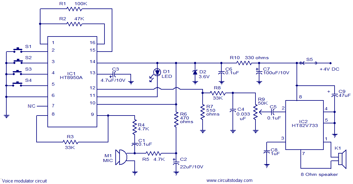
This is a very versatile voice modulator circuit using IC HT8950A from Holtek Semiconductors. The IC is capable of creating 7 upward or downward steps on the frequency of the input voice at a rate of 8Hz. There is also two special variation effects namely Vibrato mode and Robot mode. This circuit finds a lot of application in systems like telephone, speech processors, toys, mixers etc. A microphone is used to pick up the input voice. Push button switches S2 and S3 can be used for the upward and downward frequency stepping .Push button switch S1 can be used to activate Vibrato mode and push button switch S4 can be used to activate the Robot mode. IC HT82V733 (also from Holtek) is used to amplify the output of the voice modulator.LED D1 indicates the voice level.
Circuit diagram.
Notes.
The circuit can be assembled on a Vero board.
Do not give more than 4.5v to the circuit.
Switches S1 to S4 can be miniature push button switches.
Posted by Jayesh Yewale
Posted on 12:07:00 PM
with 2 comments
Description.
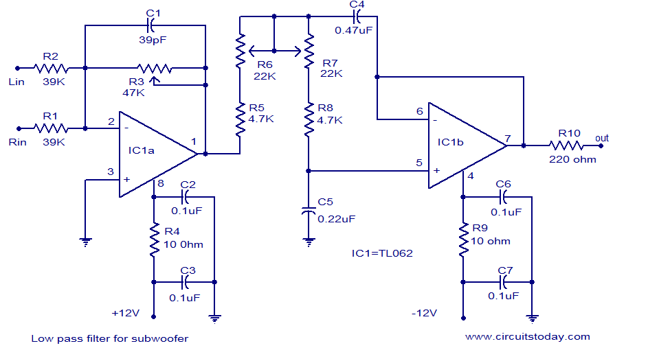
Many low pass filter circuits for subwoofer are given here and this is just another one. The circuit given here is based on the opamp TL062 from ST Micro electronics. TL062 is a dual high input impedance J-FET opamp which has very low power consumption and high slew rate. The opamp has excellent audio characteristics and is very suitable for this circuit.
Out of the two opamps inside TLC062, first one is wired as the mixer cum pre amplifier stage. The left and right channel are connected to the inverting input of IC1a for mixing. The gain of first stage can be adjusted using POT R3.The output of the first stage is connected to the input of second stage through the filter network comprising of components R5,R6,R7,R8,C4 and C5. The second opamp (IC1b) serves as a buffer and the filtered output is available at the pin 7 of the TLC062.
Circuit diagram.
Power supply for the circuit.
Notes.
Assemble the circuit on a good quality PCB.
The circuit can be powered from a +12/-12 V DC dual power supply.
Posted by Jayesh Yewale
Posted on 10:59:00 PM
with No comments
Description.
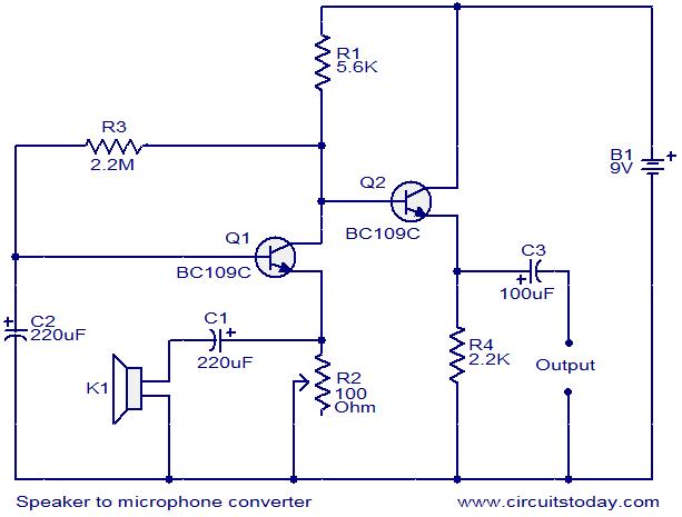
This circuit is a simple approach for converting a loud speaker into a microphone. When the sound waves fall on the diaphragm of a speaker, there will be fluctuations in the coil and there will be a small proportional induced voltage. Usually this induced voltage is very low in magnitude and useless. Here in the circuit the low voltage is amplified using transistors to produce a reasonable output. The transistor Q1 is wired in common base mode and produces the required voltage gain. The transistor Q2 is wired as an emitter follower to produce enough current gain. The voice quality of this circuit will not be as much as a conventional microphone but quite reasonable quality can be obtained. To set up the circuit, keep the preset R2 at around 10 Ohms and connect the battery. Now adjust R2 to obtain the optimum sound quality.
Circuit diagram with Parts list.
Notes.
Assemble the circuit on a general purpose PCB.
Power the circuit from a 9 V PP3 battery.
A 3 inch speaker can be used as K1.
All capacitors must be rated at least 15V.
An 8 Ohm speaker or head phone can be connected at the output to hear the picked sound.
Posted by Jayesh Yewale
Posted on 1:24:00 PM
with No comments
Description.
Here is the simplest scheme for converting a CD ROM drive of your computer to a Audio CD player.The minimum requirement for the player is that, it should have a audio output and skip button. Luckily most of the Cd ROM’s are equipped with both of these.
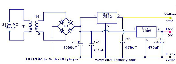
The CD ROM drive needs two voltages ,12V & 5V for its operation.So the main objective is to build a suitable power supply for the CD ROM drive.The IC1 (7812) together with associated components produce a regulated 12V DC.The IC2 (7805) together with associated components produce a regulated 5V DC.These voltages as well as ground can be connected to the corresponding voltage pins of the CD ROM drive using a male type CD ROM drive power connector.The 12V can be connected to the yellow wire of connector, 5V to red wire and GND to black wire as shown in figure1.Now the power supply is ready.
Testing.
Make the circuit as shown in the circuit diagram.Power up the circuit after connecting the power connector to the CD ROM drive. Now the power LED of the drive will glow.Insert the audio CD.Now the music will be available at the audio output socket of the drive.It can be heared using a headphone.The skip button of the drive can be used to play next song.
By connecting the audio output to a power amplifier you can enjoy the music in a greater wattage.
Click Here! to get the amplifier circuits suitable for this project.
Circuit Diagram with Parts list.
Notes.
For car stereo applications you don’t need the transformer,rectifier and the 7812 regulator.12V will be available from battery.You just need to produce a 5V from it using a 7805 based regulator. Connect the corresponding voltages to the connector as shown in figure 1 and connect the connector to drive.Done.
The amplifier for the car audio CD player must be one operating from 12V.
Do not connect the voltages to CD ROM drive in wrong polarity.Double check the voltages using a multimeter. Wrong polarity could easily damage the drive.
Posted by Jayesh Yewale
Posted on 1:16:00 PM
with No comments
Description.
With this compact FM adaptor circuit plugged into the audio out of your cassete player or i Pod out put,you can listen your favorite music on your car stereo.This circuit is very useful if your car stereo doesnot have an auxillary in socket.The circuit is nothing buy an short range FM transimitter.
The FM transmitter circuit is based on low power NPN transistor 2N2222.The tank circuit consisting of L1 & C1 producess the necessary oscillations at the collector of Q1.The capacitance C4 , resistance R3 & R4 performs the function of mixing the stereo out put from theaudio player or i-Pod.The emitter resistance R2 provides sufficient stability to the circuit.It also limits the collector current to increse the battery life.
Circuit diagram with Parts list.
Notes.
Use a 28SWG , 10 cm insulated copper wire as antenna.
For L1.make 8 turns of 20 SWG insulated copper wire on a 5mm dia plastic former.
Power the circuit from a 3V battery.
Assemble the circuit on a good quality PCB or common board.
Posted by Jayesh Yewale
Posted on 12:27:00 AM
with No comments
Description.
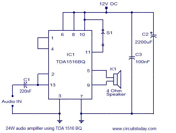
Here is the circuit diagram of a simple 24W mono amplifier using IC TDA1516.The TDA1516 is an integrated class B power amplifier in a 13 pin SIL package. The IC has many useful features such as short circuit protection, load dump protection, thermal protection, reverse polarity protection etc. Here the IC is wired in BTL mode to deliver 24W of power into a 4 ohm speaker. This amplifier can be operated from a 12V DC supply and this makes it suitable for car audio applications.
Circuit diagram with Parts list.
Notes.
Assemble the circuit on a good quality PCB.
The amplifier can be powered using a 12V DC supply.
Posted by Jayesh Yewale
Posted on 12:22:00 AM
with 1 comment
Description.
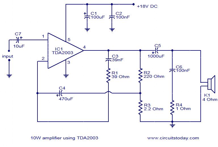
Here is the circuit diagram of a 10W audio amplifier using the popular TDA2003 IC from SGS Thomson. The IC can easily deliver 10W to a 4 Ohms load at 18V DC supply voltage. The IC can be also operated from 12V and that makes it applicable in car audio systems. The useful features of TDA2003 includes short circuit protection between all pins, thermal overload protection, low harmonic distortion, low cross over distortion etc.
The circuit given here is designed as per the datasheet from the manufacturer and found to be working fine. Capacitor C7 performs the job of input DC decoupling.R2 and R3 is used to set the gain of the amplifier.C3 and R1 determines the upper cut off frequency.C6 and R4 and meant for increasing stability at high frequencies. Capacitor C5 couples the output to the speaker.
Circuit diagram with Parts list.
Notes.
It is better to use a PCB for assembling this circuit.
PCB layout for this circuit can be found on the datasheet of TDA2003.
Use 18V DC for powering this circuit.
Input ground and output ground must be properly decoupled.
Posted by Jayesh Yewale
Posted on 12:16:00 AM
with No comments
Description.
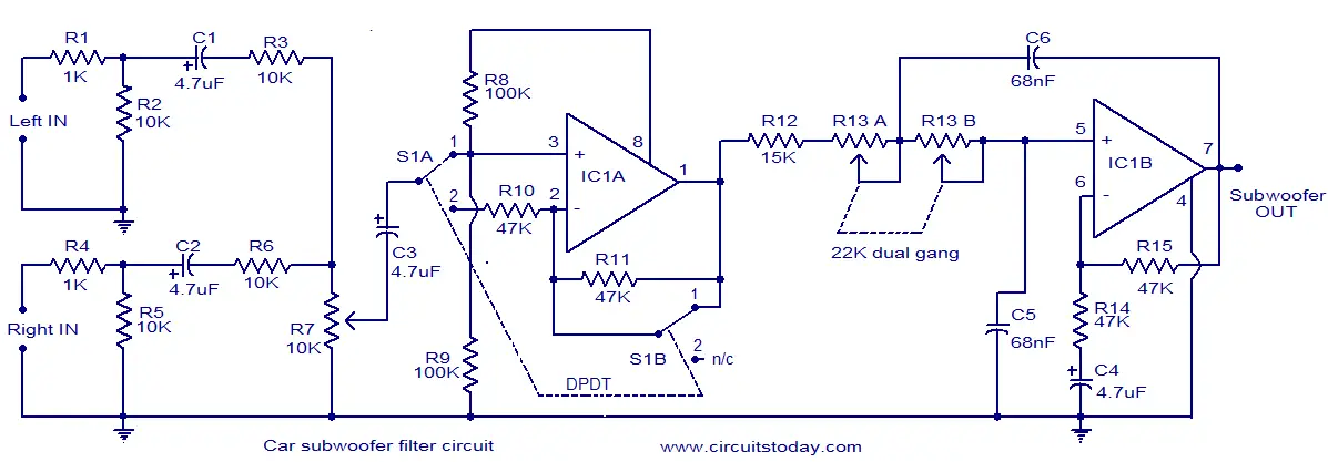
Here is the circuit diagram of a simple subwoofer filter that can be operated from a 12V DC supply. Such a circuit is very useful in automobile subwoofer applications. The circuit is nothing but a low pass filter whose pass frequency can be adjusted between 60 to 160 Hz.
The circuit is designed around the TL072 dual BIFET opamp IC. Out of the two opamps inside the chip, IC1A is wired as a buffer. The left and right audio inputs after mixing is fed to the input of the IC1A using the DPDT switch S1. Switch S1 is the phase control switch which can be used to make the subwoofer in phase with other speakers. When S1 is in position 2, 180 degree phase shift will be induced.POT R7 can be used for controlling the level. IC1B forms the low pass filter whose pass frequency can be controlled by adjusting the dual gang POT R13.
Circuit diagram . Notes.
Assemble the circuit on a good quality PCB.
The circuit can be powered from 12V DC.
IC1 must be mounted on a holder.
S1 is a DPDT switch.
R13 should be a dual gang linear POT.
C5 and C6 must be polyester capacitors.
POT R13 can be used for adjusting the pass frequency.
Posted by Jayesh Yewale
Posted on 12:15:00 AM
with 1 comment
Description.
This is just another 20W audio amplifier circuit , but this time based on the LM1875 audio amplifier IC from National Semiconductors. With a 25V dual power supply LM1875 can deliver 20W of audio power into a 4 ohm speaker. The LM1875 requires very less external components and has very low distortion. The IC is also packed with a lot good features like fast slew rate, wide supply voltage range, high output current, high output voltage swing, thermal protection etc. The IC is available in TO-220 plastic power package and is well suitable for a variety of applications like audio systems, servo amplifiers, home theatre systems etc.
Posted by Jayesh Yewale
Posted on 12:10:00 AM
with No comments
Car Audio Amplifier Circuit:
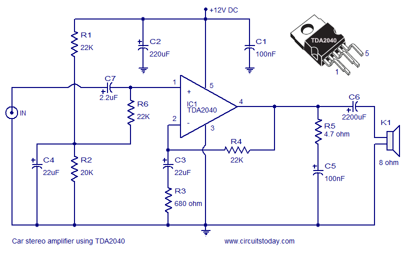
Given below is a car stereo amplifier circuit using audio amplifier IC – TDA2040
Description of the circuit:
A car stereo amplifier circuit using TDA2040 is shown here. TDA2040 is a monolithic integrated audio amplifier that operates in Class AB mode. The IC has built in circuitry for short circuit protection and thermal shut down and more over it can be operated from a single supply too. The amplifier can deliver 12 watts into to a 8 ohm speaker.
In the circuit the IC is wired in order to operate from the cars 12V line. Capacitor C7 is the input DC decoupling capacitor and R4 provides feedback. Network consisting of resistor R5 and capacitor C5 provides high frequency stability and prevents any chance of oscillation. Capacitor C6 couples the ICs output to the speaker. C2 and C1 are power supply filters.
Circuit diagram of car stereo circuit using TDA2040
Car amplifier circuit diagram
Notes.
Quality of the PCB is a very crucial factor in the amplifiers performance.
The amplifier can be operated from cars 12V line.
Heat sink is necessary for TDA2040.
All electrolytic capacitors must be rated 15V.
Only one channel is shown here. For stereo application you must make one more identical copy
Posted by Jayesh Yewale
Posted on 3:57:00 PM
with No comments
19 Watts Simple Amplifier Circuit
Description
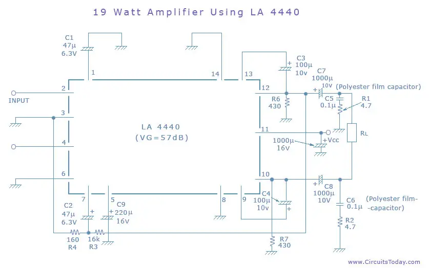
This is a 19 watt simple amplifier circuit diagram using IC LA4440 from Sanyo.It uses very less components other than the IC LA4440.A very high quality circuit with respect to its cost and ideal for beginners.
Here IC LA 4440 is wired as a bridge amplifier to deliver a 19 W Rms on a 4 Ohm speaker. The IC has built in thermal, over voltage and short circuit protection.The IC also incorporates a audio muting function,but that is not used here.
Notes .
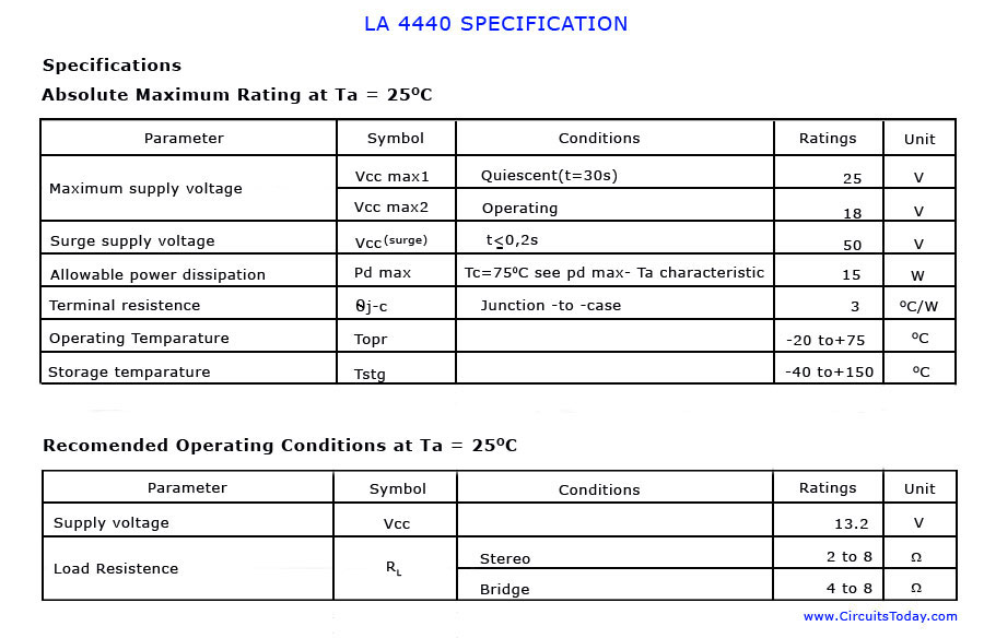
Use a 12 V DC power supply able to deliver at least 3A current . IC can with stand up to 25 volt , but I prefer it should not be nothing more than 16V.
Don’t forget to fit a proper heat sink with IC.
Assemble the board on a good quality PCB.Carefully understand the specifications of LA 4440 given below before proceeding
Use a 4 Ohm speaker as load. 8 Ohm speaker can also be used but the power output will drop to half (9.5 W) .
For stereo assemble two copies of the amplifier given here.
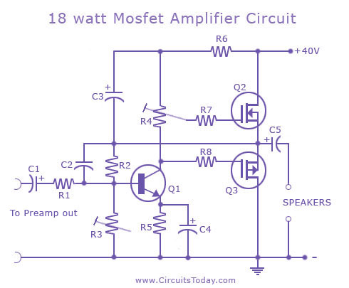
This circuit is an audio amplifier capable of delivering a decent output power with a minimum no: of parts , with considerable sound quality.
The amplifier employs only one transistor and two MOSFETs and few resistors and capacitors in a shunt feedback scheme.This tiny circuit can can deliver a whopping 18Watts into 8 Ohm speaker or 30W into a 4 Ohm speaker.
To get such a good performance and stability out of few components, a high quality well regulated DC power supply is necessary. This is very essential for reducing noise and getting a constant output power on varying loads. A good DC voltage regulator able of providing more than 2 Amps @ 40V can be used.You can expect such a power supply design very soon here in the power supply section.
Tips.
Assemble the board on a good quality PCB.Use a preamplifier board with tone control prior to this amplifier to get better performance. If you don’t want, then no problem because this amplifier circuit has enough punch with in it.
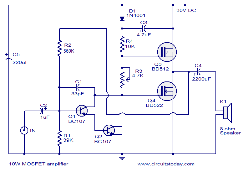
The diagram shown here is of a 10W MOSFET audio amplifier circuit that requires only a single supply. Single rail supply is seldom used in Class-B power amplifiers. Anyway, for low power applications like this it’s quite fine. Actually I got this circuit from an old cassette player that is still working and I am publishing it as it is. The powers MOSFETs BD512 and BD522 are obsolete now and so you may use any other matching power MOSFETS instead of them.
Transistors Q1 and Q2 is wired as a Darlington pair works as the preamplifier. Preset R3 controls the quiescent current while R2 provides feedback. Output is coupled to speaker through capacitor C4. Capacitor C5 is the power supply filter and C2 is the input DC decoupling capacitor.
Mosfet audio amplifier Circuit diagram
10 watts mosfet amplifier
Notes.
The circuit can be assembled on a vero board.
Use 30V DC for powering the circuit.
Do not expect much performance from this amplifier.
Capacitors C3, C4, C5 must be rated 50V and C2 can be 10V.
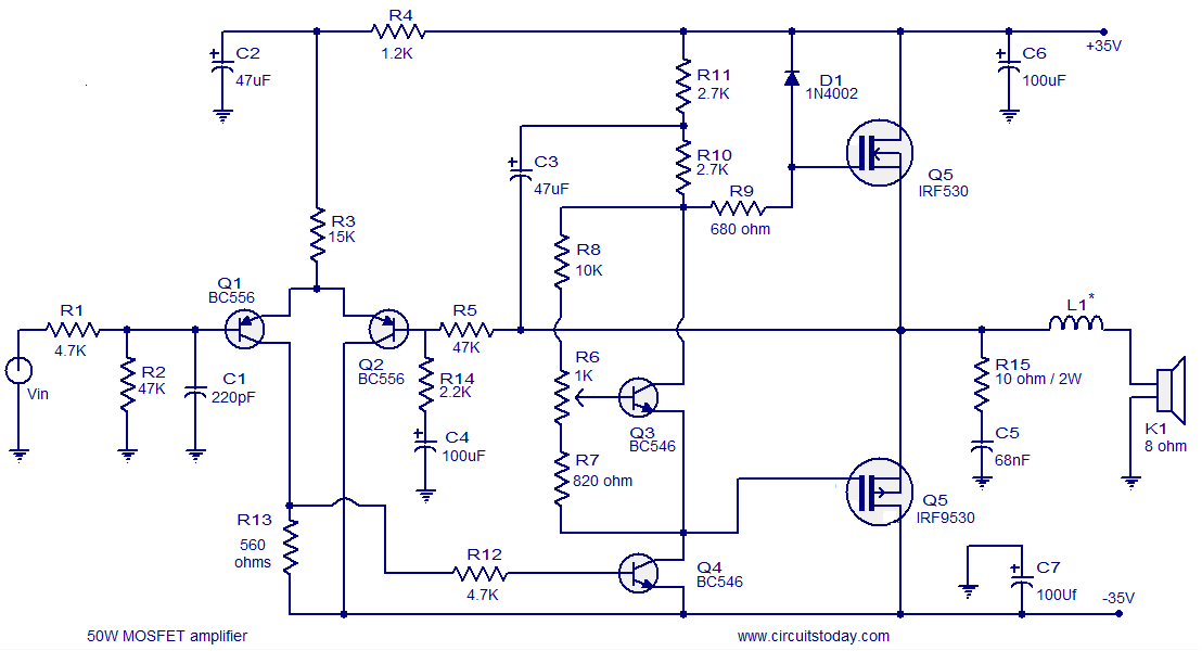
The first stage of the amplifier is a differential amplifier based on transistors Q1 and Q2. Capacitor C8 is the input DC decoupler, R1 limits input current and capacitor C1 bypasses unwanted high frequencies. The second stage is the driver stage consisting of transistors Q3 and Q4. Output stage is a complementary push pull stage based on MOSFETs IRF530 and IRF9530.Output is coupled the speaker using the inductor L1. Network comprising of R15 and C5 is meant for noise reduction. Capacitors C6 and C7 are power supply filters. Preset R6 is meant for adjusting the quiescent current.
50 Watts Mosfet Amplifier Circuit diagram.
Mosfet amplifier circuit – 50 watts
Notes:
Assemble the circuit on a good quality PCB.
Use +/-35V DC dual supply for powering the circuit.
For L1 make 12turns of enameled copper wire on a 1cm dia: plastic former.
C6 and C7 must be rated 50V; other electrolytic can be 10 or 15V.
Heat sink is necessary for the MOSFETs. A 8x4x4 inch finned Aluminum heat sink will do. There is no such thing as a heat sink that is too large
Posted by Jayesh Yewale
Posted on 3:51:00 PM
with 1 comment
Power Amplifier Circuit – 25 Watts
Description
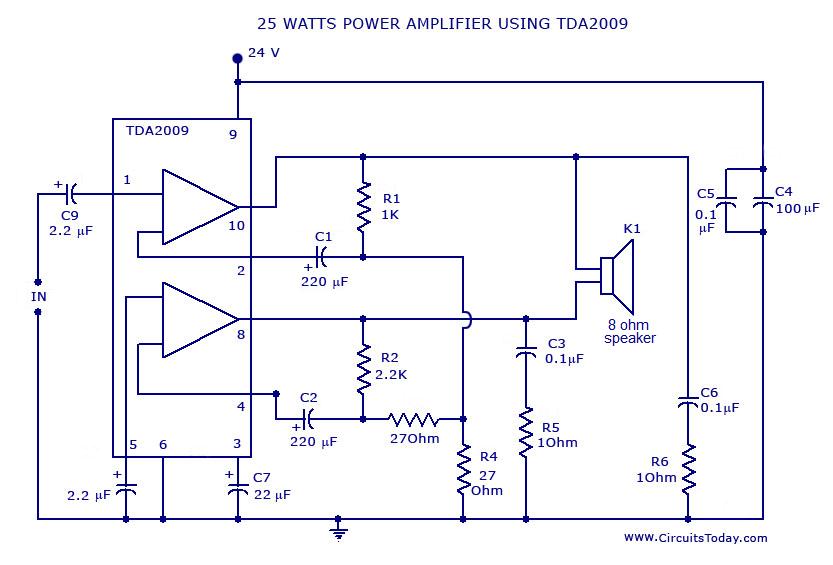
Here is the diagram of a 25 Watt power amplifier circuit made of TDA 2009 IC.TDA 2009 has two channels each rating 12.5 watts on 4 Ohm load.Here the two channels are bridged to get a single out put channel weighting 25 W.
TDA 2009 IC has also built in features such as short circuit protection,thermal protection, overload protection etc using very low external components.The most interesting factor I see about this IC is that it require no dual supply.
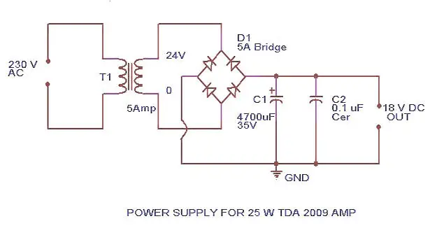
Power Amplifier Circuit Diagram and Power Supply Circuit Schematic
Notes
Do not connect more than 24 V to TDA 2009.
If 5 ampere bridge is not available make one using four 5 A diodes.
Fit a proper size heat sink to TDA 2009
Do not operate the circuit without heat sink.
For volume control connect a 10K pot
All capacitors in this circuit must be rated above 25 V
Posted by Jayesh Yewale
Posted on 3:49:00 PM
with 1 comment
Mini Amplifier Circuit
Description
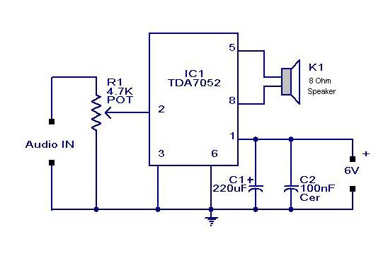
Here is a simple and humble 2 Watts mini audio amplifier circuit suitable for small pocket radios and other portable audio gadgets.The circuit is based on Phillips Semiconductors IC TDA 7052.The amplifier can be run even from a 3V Mercury button cell.This makes it ideal for battery operated gadgets.
The IC TDA7052 is a mono output amplifier coming in a 8-lead DI package (DIP). The device is mainly designed for battery-operated portable audio circuits. The features of TDA 7052 include ,no external components needed, no switch-on or switch-off click sounds , great overall stability ,very low power consumption(quiescent current 4mA) , low THD, no heat sinks required and short-circuit proof.
The gain of TDA 7052 is fixed internally at 40 dB. . To compensate the reduction of output power due to low voltage supply the TDA7052 uses the Bridge-Tied-Load principle
(BTL) which can provide an output of around 1 to 2 W Rms(THD = 10%) into an 8 Ohm load with a power supply of 6 V.
In the circuit the potentiometer can be used to control the volume.Capacitor C1 and C2 are meant for filtering the supplyvoltage if a battery eliminator is used as supply source.For operations using a battery C1 and C2 are no necessary.
Mini Audio Amplifier Circuit Diagram with Parts List .
Mini Audio Amplifier Circuit Diagram
Notes.
Assemble the circuit on a good quality PCB or common board .
If you are a little expert, you can assemble the circuit in a match box including the speaker



 .12V will be available from battery.You just need to produce a 5V from it using a 7805 based regulator. Connect the corresponding voltages to the connector as shown in figure 1 and connect the connector to drive.Done.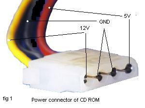
 .
. .The tank circuit consisting of L1 & C1 producess the necessary oscillations at the collector of Q1.The capacitance C4 , resistance R3 & R4 performs the function of mixing the stereo out put from theaudio player or i-Pod.The emitter resistance R2 provides sufficient stability to the circuit.It also limits the collector current to increse the battery life.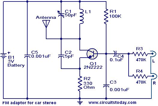
 circuit , but this time based on the LM1875 audio amplifier IC from National Semiconductors. With a 25V dual power supply
  can deliver 20W of audio power into a 4 ohm speaker. The LM1875 requires very less external components and has very low distortion. The IC is also packed with a lot good features like fast slew rate, wide supply voltage range, high output current, high output voltage swing, thermal protection etc. The IC is available in TO-220 plastic power package and is well suitable for a variety of applications like audio systems, servo amplifiers, home theatre systems etc.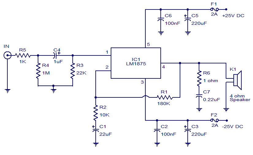

 .
.