A tachometer is nothing but a simple electronic digital transducer. Normally, it is used for measuring the speed of a rotating shaft. The number of revolutions per minute (rpm) is valuable information for understanding any rotational system. For example, there is an optimum speed for drilling a particular-size hole in a particular metal piece; there is an ideal sanding disk speed that depends on the material being finished. You may also want to measure the speed of fans you use.
Here is an easy-to-construct temperature indicator-cum-controller that can be interfaced with a heater coil to maintain the ambient room temperature. The controller is based on Atmega8535 microcontroller, which makes it dynamic and faster, and uses an LCD module to display and two keys to increase or decrease the set values.
Digital wall clocks, table clocks and desk clocks with pointer or LCD display are readily available in the market. Here we present a clock that can be built in a small budget using AT89C2051 microcontroller. Additional feature of the clock is that the time display is visible even in the dark.
The circuit that uses microcontroller AT89C51 can control four devices from a distance of upto 30 metres wirelessly. An LCD module is used to show the device number and preset control time at the transmitter module.
Posted by Jayesh Yewale
Posted on 9:45:00 PM
with No comments
Robots, as anyone who has ever attempted to build or buy or fix a robot knows, tend to be expensive. This presents a problem for people who want to start learning about robotics, because getting a foot in the door with an actual robot to work on generally involves a substantial up-front investment in hardware. And for places where teachers and students don't have huge piles of money to throw at technology, this can mean that robots just don't happen.
The African Robotics Network (AFRON) and IEEE Robotics and Automation Society (RAS) collectively sponsor a biennial design challenge to "collaboratively create an educational robot that is an order of magnitude less expensive than existing products, to inspire young people around the world." For 2013/2014, MIT took home a win with their MIT SEG robot, a 3D-printed, Arduino-based wheeled robot that can be built for $20 in five steps with no training or tools.
The completed MIT SEG is shown in the picture above; below is an image of the unassembled robot in its entirety:
All you have to do to go from this to robot is fold up the chassis (the squareish bits at the lower left), fold the wheels together, fit the electronics in, stick the wheels onto the servos, and that's it, you're done. Here's the bill of materials:
MIT points out that if you don't go with a breakout board for the Arduino and instead wire-wrap the headers directly, you can drop the cost by about $2.50 per bot. You also need a programmer and a charger, which together will run you another $18.20, but these can be shared among multiple robots.
So great, you've got a robot that's easy to make and is dirt cheap. What can it do? Out of the box, MIT SEG includes an Arduino compatible drag-and-drop graphical programming interface. The LED and photosensor can be used to determine whether the robot is looking at something black, white, or gray, meaning that you can do line-following and some obstacle avoidance right away, and MIT has put together a bunch of examples and an entire curriculum that classrooms can follow. Plus, since the robot has an Arduino for a brain, you can leverage all of the hardware (and the community) that's been plugging into Arduinos for the last few years.
The Ultra Affordable Educational Robot Project Design Challenge also includes categories for Software, Curriculum, and Community Challenges.
"The AFRON organizers and RAS sponsors admire the ingenuity of the submissions in all categories," said Ken Goldberg, a roboticist at UC Berkeley who co-founded AFRON with Ayorkor Korsah, a professor of computer science at Ashesi University, in Ghana. Goldberg noted that two winning projects from Africa, PanyaBot (Kenya) and ARX LollyBot (Ghana), continue to make major advances in the Software and Community Challenge categories. "We look forward to connecting all the participants to share ideas and designs for next steps via the AFRON network, which anyone worldwide can join at no cost," he said.
Posted by Admin
Posted on 6:07:00 PM
with 1 comment
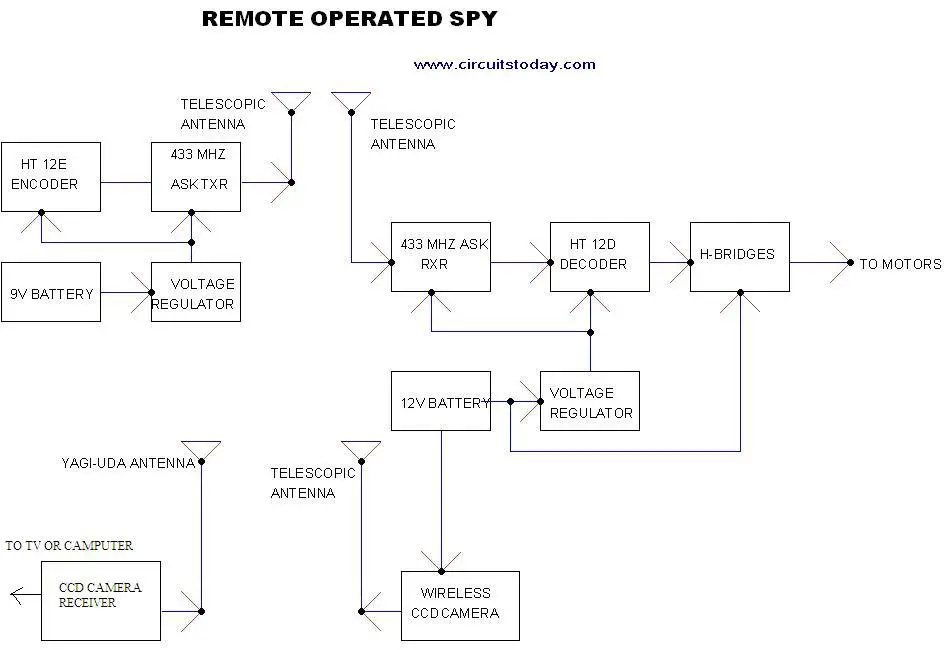
Here is a remote operated spy robot
circuit which can be controlled by using a wireless remote controller.
It can capture audio and video information’s from the surroundings and
can be sent to a remote station through RF signals. The maximum range is
125 meters. It overcomes the limited range of infrared remote
controllers. This robot consists of mainly two sections. They are
explained in detail below.
Remote Control Operated Spy Robot Circuit – Block Diagram
Remote Control Operated Spy Robot Circuit - Block Diagram
1. Remote Control Section
The circuit uses HT 12E, HT 12D encoder
and decoder. 433MHz ASK transmitter and receiver is used for the remote
control. H-bridge circuits are used for driving motors. Two 12V
DC/100RPM gear motors are used as drivers. The working of the circuit is
as follows.
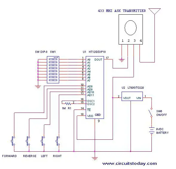
When we are pressing any key in remote
controller the HT 12E generate 8 bit address and 4 bit data .The DIP
switches are used for setting the address. Then the ASK transmitter
sends the 8 bit address and 4 bit data to the receiver Then the ASK
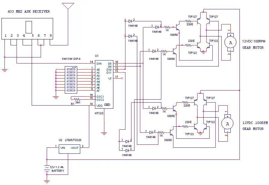
receiver receives the 8 bit address and 4 bit data and HT 12D decoder
decodes the data, thus enabling the appropriate output. Thus the output
signals that are generated controls the H-bridge which then rotates the
motors.
The 433 MHZ ASK transmitter and
receivers are extremely small, and are excellent for applications
requiring short-range RF remote controls. The transmitter module is
only 1/3rd the size of a standard postage stamp, and can
easily be placed inside a small plastic enclosure. The transmitter
output is up to 8mW at 433.92MHz. The transmitter accepts both linear
and digital inputs and can operate from 1.5 to 12 Volts-DC, and makes
building a miniature hand-held RF transmitter very easy. The 433 MHZ
ASK transmitters is approximately the size of a standard postage stamp
433 MHZ ASK receivers also operate at 433.92MHz, and have a sensitivity of 3uV. The receiver operates from 4.5 to 5.5 volts-DC.
In this project we are using a wireless
CCD camera. Now these types of cameras are commonly available in the
market. It works on 12VDC supply.
The 12 Volt DC supply is taken from the
battery placed in the robot. The camera has a receiver, which is placed
in the remote station. Its output signals are in the form of audio and
video. These signals are directly connected to a TV receiver or a
computer through a tuner card.
Remote Operated Spy Robot - Remote Control Section
Components Required
IC
HT 12E
1
HT 12D
1
LM 7805
2
TRANSISTOR
TIP 127
4
TIP 122
4
S 8050
4
DIODE
1N 4148
8
RESISTOR
1K
4
220E
4
39K
1
1M
1
ASK TRANSMITTER
433 MHz
1
ASK RECEIVER
433 MHz
1
DIP SWITCH
2
PUSH TO ON SWITCH
4
GEAR MOTOR
12V DC 100rpm
2
BATTERY
12V 1.3 Ah rechargeable
1
9V
1
WIRELESS CCD CAMERA
1
Construction
The steps for the construction are…
1. Take a hylam sheet with (20cm*15cm) size.
2. Fix two gear motors (12VDC 100rpm) in the hylam sheet by using aluminum pieces and nut bolts as shown in the figure below.
3. Fix the ball castor as shown in the figure below.
Construction of Remote Operated Spy Robot Circuit
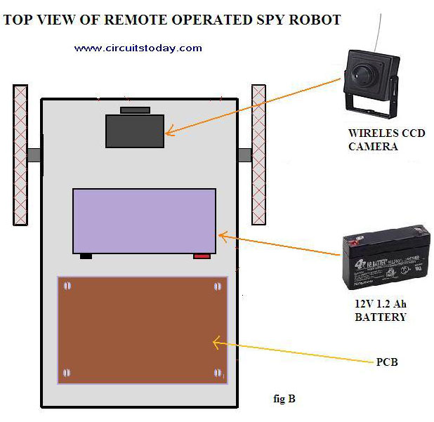
4. Then fix the battery (12VDC 1.2Ah) on the top of the spy robot as shown in the figure below.
Construction of Remote Operated Spy Robot Circuit – Top View
5. Connect two motors to the PCB. The PCB is then connected to the battery.
6. Connect the wireless CCD camera to the battery.
7. Connect the camera receiver to the TV or computer. Video information’s will thus appear in the screen.
8. Switch on the remote controller and control the spy robot
Posted by Jayesh Yewale
Posted on 10:48:00 AM
with 4 comments
Robotic Car is a miniature prototype car powered by batteries whose various movements can be control either manually or automatically, or the combination of both. Here the command is given through keyboard; it would have been better if we used IR remote control or something of that kind rather than using keyboard for commanding. However, by realizing the complexities we have made simple using keyboard.
Block diagram of the project:
Some photographs of this model:
Robotic car model
Robotic car model
Project Description:
Keyboard section:
There are six switches in this section. They are
Turn left.
Turn right.
Stop.
About turn.
Park left.
Park right.
Circuit diagram of keyboard is shown bellow.
Keyboard circuit of the Robotic car
Car section:
There are many sub sections in this section. They are
Motor:
We are using a 5V dc motor to drive the vehicle. The speed of the vehicle and its strength is controlled by the proper use of pulley. The rear wheel of the vehicle is connected to this motor through a pulley. This motor is meant for moving the vehicle both in forward and backward direction. Microcontroller (8051) controls the forward and backward movement of the vehicle in the following manner:
Circuit diagram of Motor connection
Here in the above circuit, T1, T2, T3, T4 are the NPN power transistor (2N3055). A0, A1, A2, A3 are the signals coming from the micro controller. With the specific combination of A0, A1, A2, A3 we can change the direction of rotation of motor as follows:
Case I: When A0=high; A3=high; & A1=low; A2=low The motor rotates in clockwise direction Case II: When A0=low; A3=low; & A1=high; A2=high The motor rotates in anti-clockwise direction Case III: When A0=low; A3=low; A1=low; A2=low The motor stops the rotation.
Stepper Motor:
A 5V dc Stepper motor is fixed at the front wheel lever directly. It enables the vehicle to rotate left or right through any angle. The electrical pulses generated from the micro controller directly control the movement of the stepper motor.
A stepper motor is an electromagnetic device that translates electrical pulses into mechanical movement.
Circuit diagram of stepper motor interfacing is shown bellow. First 4 pins port 2 is connected to motor. Power transistors must be connected to drive the motor.
Interfacing stepper motor to 8951
Transmitter and Receiver:
We are fitting three IR sensors along with the transmitter at the front of the vehicle in such an angle that the sensor will detect the signal only if certain obstacle is placed at the front of the vehicle at a distance of around 3 inches. This range of detection can be further adjusted by adjusting the amplitude of transmitter or by adjusting the angle of alignment between the transmitter and the sensor. All these sensors work independently and can sense the obstacle that comes at the front of the vehicle through different position independently. Thus with these three sensors, we are able to cover the entire frontal view of the vehicle at a distance of 3 inches. The circuit diagram of the transmitter and the receiver are given below:
Transmitter:
Transmitter circuit is used to transmit the IR rays. The IR LED emit infrared light switch is put on in the transmitting unit. To generate IR signal 555 IC based astable multivibrator is used. Infrared LED is driven through transistor BC 177.
Circuit diagram of IR Transmitter
Receiver:
The receiving unit consists of a sensor and its associated circuitry, which detects IR pulses transmitted by IR-LED. As a result the monostable is triggered and a short pulse is applied to port 2.5 of 8951. Circuit diagram is shown below. Do the same circuit two more times and connect it into 6 and 7 of port 2.
Circuit diagram of IR Receiver
Working:
Manual mode:
In manual mode, the vehicle can be commanded through a wireless microphone to
Turn left.
Turn right.
Stop.
About turn.
Park left.
Park right.
1. Turn left:
On getting the command of turn left, the vehicle turns towards left with 30 degree and after 3sec; it comes back to the original position. The degree in which the vehicle rotates, and the timing of coming back to the original position can be further adjusted based on our desired.
2. Turn right:
Right turn is same as that of left turn except for the fact that on getting command it turns towards right. All the modifications those are valid for the left turn is also true in this case.
3. Stop:
Once the vehicle gets the command for “stop” it remains in the idle state. There after its control is hand over to the beginning state.
4. About turn:
In about turn, the vehicle turns backward in two steps same as we did in our normal car. In first step the vehicle move only 90 degree and repeat the same in second step.
5. Park left:
On getting the command to park left, the vehicle parks on the left side of the road in a single step.
6. Park right:
Park right is same as that of park left, but here in this case, it parks towards the right side of the road.
You can also add two modes to the present design using two more switches. They are
Auto Mode:
In auto mode, the vehicle can be programmed to move at a particular place and park there. While moving, if any obstacle comes at the front of the vehicle, it will deviate its path automatically and come to the original path. The place where the vehicle is desired to move is the choice of the user; it can be either straight or bent path.
In our model, we have put three sensors at the front of the vehicle, so it is up to the user that, by what angle the vehicle should deviate. Further, it can be programmed on which side it should deviate, either left or right based on our desired. To alert the user that the vehicle is deviating an obstacle, a musical sound system is fitted in the vehicle, so that whenever it is deviating any obstacle, it will also play a music simultaneously.
Hybrid Mode:
It is the combination of both auto and manual mode. Here the vehicle can be commanded to move, to turn left or right. Further, while moving, if any obstacle comes on its path, it will deviate and come to its original path after deviating. However, if so happen that before coming to the original path, the sensor detects another obstacle; it will halt the movement of the vehicle, and play an alarm music as long as the obstacle is detected. The moment second obstacle is removed; the vehicle will continue its earlier execution.