Search This Blog

Powered by Blogger.

Translate

[TC] DIY Auto-Balancing Surface using Servo Motors

Using a touch screen, these DIYers built an self balancing surface which automatically tilts itself based upon the position of any object placed upon it.  In the video demo, the surface automatically adjusts to the ball, keeping it directly the the center of the screen, reacting quickly when the object is manipulated.
As you can see in the video, the screen outputs data which is sent back to the servos which adjust their axis accordingly.
We carry many servos in varying speeds and sizes in Hack-n-mod store.


This demo shows a Ball and Plate demo done by Francesco Prosperi at the Retis Lab of the Scuola Superiore S. Anna in Pisa.

The demo uses the Flex boards hosting a Microchip dsPIC DSC that pilots two servomotors. The ball position is taken by using a touchscreen!

Updated Apr 2010 - we released a new version of the Ball & Plate available for purchase! Just check
http://www.evidence.eu.com/products/a...
The new system is completely supported by the Scicoslab Code Generator


Source" http://www.youtube.com/

[TC] Breathalyzer circuit using 8051

Alcohol Breathalyzer circuit using 8051 Microcontroller (AT89S51).

This article is about a breathalyzer circuit using 8051 microcontroller which outputs the blood alcohol content (BAC) from the breath. The BAC is displayed in percentage on a 3 digit seven segment display. The microcontroller used if AT89S51 which belongs to the 8051 family and the alcohol sensor is MQ135 gas sensor from Futurelec.

MQ135 gas sensor.

MQ135 is a stable and sensitive gas sensor which can detect  ammonia, carbon dioxide, alcohol, smoke, nitrogen dioxide etc. The sensor consists of a tin dioxide sensitive layer inside aluminium oxide micro tubes, measuring electrode and a heating element inside a tubular aluminium casing. The front end of the sensor is covered using a stainless steel net and  the rear side holds the connection terminals.
The ethyl alcohol present in the breath is oxidized into acetic acid while passing over the heating element. This ethyl alcohol falls on the  tin dioxide sensing layer and as a result its resistance decreases. This resistance variation  is converted into a suitable voltage variation using an external load resistor. The typical connection arrangement of an MQ135 alcohol sensor is shown below.
mq135 alcohol sensor
MQ135 alcohol sensor
MQ135 has different resistance values at different temperature and different concentration of gases. The manufacturer recommends to calibrate the sensor at 100ppm of ammonia or 50ppm of alcohol. The recommended value of the load resistor is between 10K to 47K.

Circuit diagram.

alcohol meter using 8051
Breathalyzer using 8051

The voltage output of the alcohol sensor is converted into a digital format using the ADC0804 (IC1). The Vref/2 pin of the ADC is held at 1.28V using the voltage divider network made of R14 and R15. Vref/2 =1.28V means the step size of the ADC will be 10mV and the output of the ADC will increment by one bit for every 10mV increment in the analog input. Refer the datasheet of ADC0804 for a better grasp. Digital out of the ADC (D0 to D7)  is interfaced to Port1 of the microcontroller. Control signals CS, RD, WR, INTR are obtained from the microcontrollers P3.7, P3.6, P3.5, P3.4 pins respectively. R9 and C1 are associated with the clock circuitry of the ADC0804.
Capacitor C3 connected between Vin+ and Vin- of the ADC0804 filters of noise (if any) in the sensor output. If C3 is not used the digital output of the ADC will not be stable. This filter capacitor will surely induce some lag in the ADC response but it is not very relevant in this entry level application. The microcontroller performs required manipulations on the ADC digital output in order to convert it into BAC % and displays it on the three digit seven segment display. Port0 of the microcontroller is interfaced to the multiplexed three digit seven segment display. The drive signals for the threes digits are obtained from the microcontroller’s P3.0, P3.1, P3.2 pins respectively.

Program.

ORG 00H
MOV P1,#11111111B
MOV P0,#00000000B
MOV P3,#00000000B
MOV DPTR,#LUT
MAIN: MOV R4,#250D
      CLR P3.7
      SETB P3.6
      CLR P3.5
      SETB P3.5
WAIT: JB P3.4,WAIT
      CLR P3.7
      CLR P3.6
      MOV A,P1
      MOV R5,A
      SUBB A,#86
      JC NEXT
      SETB P3.3
      CLR PSW.7
NEXT: MOV A,R5
      SUBB A,#115D
      JNC LABEL
      MOV A,#00000000B
      CLR PSW.7
LABEL: MOV B,#5D
       MUL AB
       MOV B,#8D
       DIV AB
       MOV B,#10D
       DIV AB
       MOV R6,A
       MOV R7,B
DLOOP:SETB P3.0
      MOV P0,#01000000B
      ACALL DELAY
      CLR P3.0
      SETB P3.1
      MOV A,R6
      ACALL DISPLAY
      MOV P0,A
      ACALL DELAY
      CLR P3.1
      SETB P3.2
      MOV A,R7
      ACALL DISPLAY
      MOV P0,A
      ACALL DELAY
      CLR P3.2
      DJNZ R4,DLOOP
      SJMP MAIN
DELAY: MOV R3,#255D
LABEL1: DJNZ R3,LABEL1
        RET
DISPLAY: MOVC A,@A+DPTR
         CPL A
         RET
LUT: DB 3FH
     DB 06H
     DB 5BH
     DB 4FH
     DB 66H
     DB 6DH
     DB 7DH
     DB 07H
     DB 7FH
     DB 6FH
END

Notes.

  • The MQ135 gas sensor requires around 5 minutes of preheat before the first use.
  • The MQ135 takes few minutes to retrace back to its normal condition after a positive test (alcohol present in the breath).
  • If there is no alcohol in the breath  the sensor output will swing back to its normal condition very fast.
  • This breathalyzer circuit is just an entry level one and is not suitable for high end applications such as law enforcement or laboratory application.
  • The logic for converting the digital output of ADC into BAC percentage was obtained using approximation techniques.

[TC] Arduino based distance sensor

Here  is a simple tutorial to build a Distance sensor which will show the distance from the distance sensor HC-SR04 ( Or any other compatible devices) to the wall or obstacles in front of the sensor in CentiMeters.This project uses a HCR-SR04 distance sensor and atmega 328 or any other atmega chip which is programmed using a arduino programming kit, SO the project is based on arduino. But our final Circuit will be a standalone circuit without attached arduino programmer.Hardware Used:

HC-SR04It is a simple Ultrasonic ranging module
hc-sr04
hc-sr04
With Specifications:

power supply :5V DCquiescent current : <2mAeffectual angle: <15°ranging distance : 2cm – 500 cmAnd whose Sequence chart is

:sequence chart

sequence chart. We can send a short ultrasonic pulse at t1 , and if any obstacles is there the received ultrasonic signal is converted to an electrical signal as Echo.  If a 10μs width trigger pulse is sent to the signal pin, the Ultrasonic module will  output eight 40kHz ultrasonic signal and detect the echo back. The measured distance is proportional to the echo pulse width and can be calculated by the formula above. If no obstacle is detected, the output pin will give a 38ms high level signal. 

Arduino : Either a Arduino Board or a Arduino IC( Atmgea 328 , Atmega 128 , Atmega 8 etc ) with a programmer is used. To know more about Arduino visit the official arduino site http://arduino.cc 

16*2 LCD
2X16 LCD
 2X16 LCD


Wiring:SO If you are going to use arduino board then please connect devices as following:FOR LCD:* LCD RS pin to digital pin 12* LCD Enable pin to digital pin 11* LCD D4 pin to digital pin 5* LCD D5 pin to digital pin 4* LCD D6 pin to digital pin 3* LCD D7 pin to digital pin 2* LCD R/W pin to ground* 10Komhs Variable resistor   with two ends to +5v and ground and the middle wipper ti LCD pin VO.If you also have back light in your LCD and  want to enable it:* LCD A to +5v , LCD K to Ground.And LCD VSS to Ground , LCD VDD to +5v.FOR HC-SR04:* VCC to +5v , Gnd to Groung* “Trig” Pin to Digital pin 7* “Echo” Pin to Digital pin 8 And if You are not using Arduino Board instead using a Arduino IC after programming it then use the following schematic: 

distance meter  

Software:

Here is a simple version of the software:

#define trigPin 7
 #define echoPin 8
void setup() {
Serial.begin (9600);
pinMode(trigPin, OUTPUT);
pinMode(echoPin, INPUT);
}
void loop() {
int timetaken, dist;
digitalWrite(trigPin, HIGH);
delayMicroseconds(1000);
digitalWrite(trigPin, LOW);
timetaken = pulseIn(echoPin, HIGH);
dist = (timetaken/2) * 0.034049 ;
if (dist >= 300 || dist <= 0){
Serial.println(“Out Of Range”);
}
else {
Serial.println(“Distance in CM: “);
Serial.print(dist);
}
delay(500);
}


Theory:

Here , we are going to calculate the distance of the sensor and any object in front of it. At t1 we send the trigger signal , and at t2 we get the echo.so dt = t2-t1And as dt is the time for the sound taken to reach to the object and return back;The exact time taken by the sound to reach the object is : dt/2Now , Normal speed of sound is: 340.29 m / s And converting it to Centimeters per Micro Seconds gives : 0.034049 CM / microsecondsThe actual distance traveled by the sound or the distance between the sensor and the object is:(dt/2) * 0.034049
Which is the exact formula used in the software.


Source: http://electronicsproject.org/ 

[TC] Ultrasonic Proximity Detector

This ultrasonic proximity detector comprising independent, battery-powered transmitter and receiver sections makes use of a pair of matched ultrasonic piezoceramic transducers operating at around 40 kHz each. This circuit can be used in exhibitions to switch on prerecorded audio/video messages automatically when a visitor evincing interest in a product comes near an exhibited product.

Fig. 1: Transmitter circuit
Fig. 1 shows the transmitter circuit. It comprises CMOS timer IC 7555 (IC1) configured as an astable multivibrator, which may be tuned to the frequency of the ultrasonic piezoceramic transmitter’s resonant frequency of around 40 kHz using preset VR1. A complementary pair of transistors T1 and T2 is used for driving and buffering the transducer while it draws spikes of current from IC1 circuit to sustain oscillations and thereby avoids any damage.

The receiver front-end (refer Fig. 2) is designed to provide a very high gain for the reflected faint ultrasonic frequency signals detected by the ultrasonic transducer. The amplifiers built around N1 and N2, respectively, provide AC voltage gain of around 80 each. These two stages should have a high open-circuit gain, wide bandwidth and very low bias current apart from being capable of single-supply operation. Quad op-amp LM324 is used here due to its low cost. For higher efficiency, you may use single op-amps such as CA3130 or CA3140.

Fig. 2: Receiver circuit


Fig. 3: Pinconfigurations oftransistors BC327and BC337
When a visitor pauses before a sistor R10 is used to meet this requirement. The filter also helps to bypass brief bursts of ambient noise in the ultrasonic range. The third stage comprising N3 works as a comparator to provide a triggering pulse when a visitor stops by. This pulse can be used to trigger a timer or a monostable, whose output may then be used to switch on the audio/video message concerning the product for a predetermined period.

When somebody comes in front of the ultrasonic piezoceramic transducer pair, the status LED (LED1) glows because of the signal reflected from the body of the visitor.

The circuit can be assembled on any general-purpose PCB. The transmitter and the receiver should be aligned such that the transmitted ultrasonic signal is optimally received by the receiver after reflection. Fig. 3 shows the pin configuration of transistors T1 and T2, while Fig. 4 shows installation of the ultrasonic piezoceramic transducer pair operating at around 40 kHz.


Source: http://electronicsforu.com/
 

Fig. 4: Installation of transducer pair

[TC] Remote controlled Spy Bot

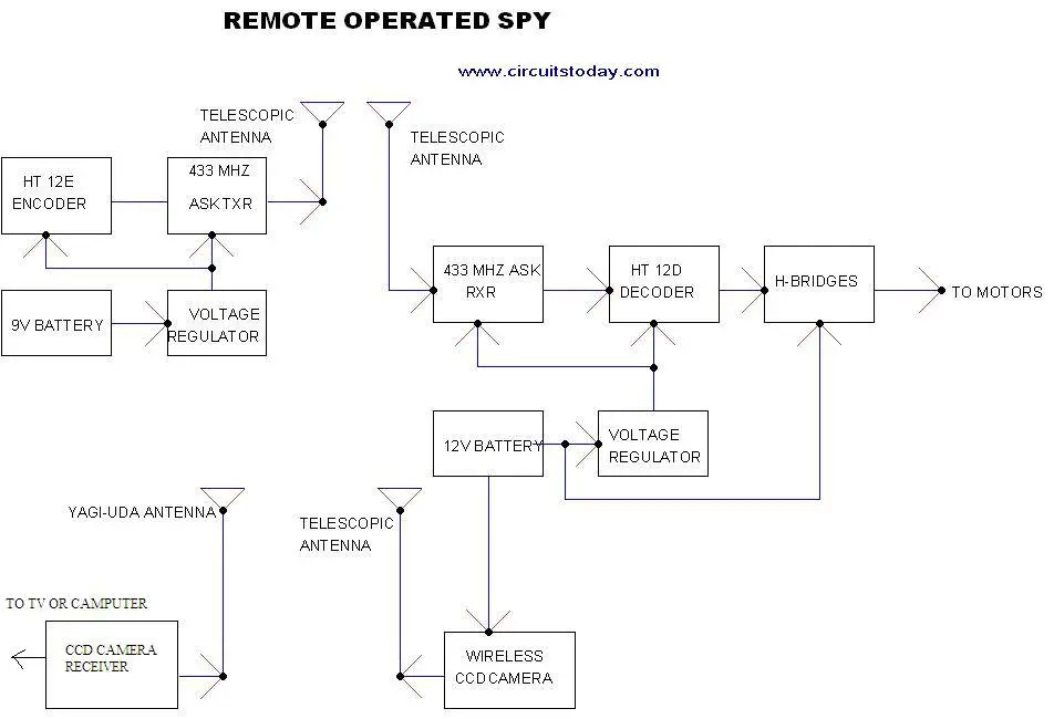
Here is a remote operated spy robot circuit which can be controlled by using a wireless remote controller. It can capture audio and video information’s from the surroundings and can be sent to a remote station through RF signals. The maximum range is 125 meters. It overcomes the limited range of infrared remote controllers. This robot consists of mainly two sections. They are explained in detail below.

Remote Control Operated Spy Robot Circuit – Block Diagram

    Remote Control Operated Spy Robot Circuit - Block Diagram
Remote Control Operated Spy Robot Circuit - Block Diagram

1. Remote Control Section

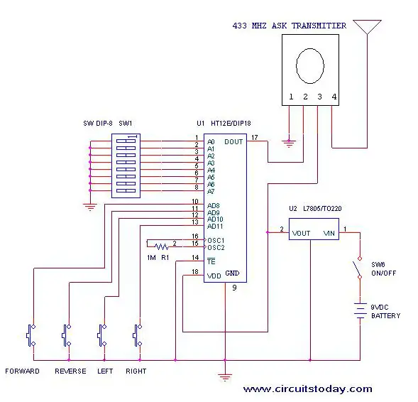
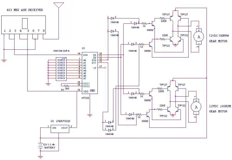
The circuit uses HT 12E, HT 12D encoder and decoder. 433MHz ASK transmitter and receiver is used for the remote control. H-bridge circuits are used for driving motors. Two 12V DC/100RPM gear motors are used as drivers. The working of the circuit is as follows.
When we are pressing any key in remote controller the HT 12E generate 8 bit address and 4 bit data .The DIP switches are used for setting the address. Then the ASK transmitter sends the 8 bit address and 4 bit data to the receiver Then the ASK receiver receives the 8 bit address and 4 bit data and HT 12D decoder decodes the data, thus enabling the appropriate output. Thus the output signals that are generated controls the H-bridge which then rotates the motors.
The 433 MHZ ASK transmitter and receivers are extremely small, and are excellent for applications requiring short-range RF remote controls.  The transmitter module is only 1/3rd the size of a standard postage stamp, and can easily be placed inside a small plastic enclosure. The transmitter output is up to 8mW at 433.92MHz. The transmitter accepts both linear and digital inputs and can operate from 1.5 to 12 Volts-DC, and makes building a miniature hand-held RF transmitter very easy.  The 433 MHZ ASK transmitters is approximately the size of a standard postage stamp
433 MHZ ASK receivers also operate at 433.92MHz, and have a sensitivity of 3uV.  The receiver operates from 4.5 to 5.5 volts-DC.
Remote-Control-Operated-Spy-Robot-Circuit-Remote-Control-Section

2. Video Transmission Section

In this project we are using a wireless CCD camera. Now these types of cameras are commonly available in the market. It works on 12VDC supply.


The 12 Volt DC supply is taken from the battery placed in the robot. The camera has a receiver, which is placed in the remote station. Its output signals are in the form of audio and video. These signals are directly connected to a TV receiver or a computer through a tuner card.
Remote Operated Spy Robot - Remote Control Section

Components Required

IC HT 12E 1
HT 12D 1

LM 7805 2
TRANSISTOR TIP 127 4

TIP 122 4

S 8050 4
DIODE 1N 4148 8
RESISTOR 1K 4

220E 4

39K 1

1M 1
ASK TRANSMITTER 433 MHz 1
ASK RECEIVER 433 MHz 1
DIP SWITCH
2
PUSH TO ON SWITCH
4
GEAR MOTOR 12V DC 100rpm 2
BATTERY 12V 1.3 Ah   rechargeable 1

9V 1
WIRELESS CCD CAMERA
1

Construction

The steps for the construction are…
1. Take a hylam sheet with (20cm*15cm) size.
2. Fix two gear motors (12VDC 100rpm) in the hylam sheet by using aluminum pieces and nut bolts as shown in the figure below.
3. Fix the ball castor as shown in the figure below.
Construction of Remote Operated Spy Robot Circuit
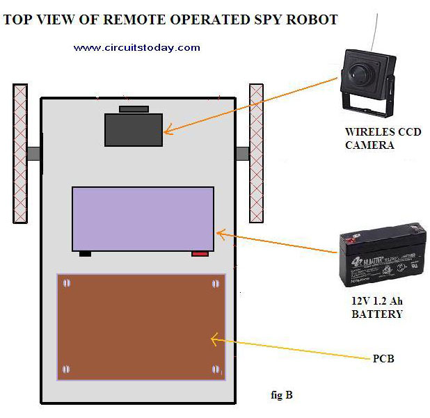
4. Then fix the battery (12VDC 1.2Ah) on the top of the spy robot as shown in the figure below.
Construction of Remote Operated Spy Robot Circuit - Top View
Construction of Remote Operated Spy Robot Circuit – Top View
5. Connect two motors to the PCB. The PCB is then connected to the battery.
6. Connect the wireless CCD camera to the battery.
7. Connect the camera receiver to the TV or computer. Video information’s will thus appear in the screen.
8. Switch on the remote controller and control the spy robot


Source: http://www.circuitstoday.com/

How to build Digital Electronic Lock

Circuit

Digital Electronic Lock

Description

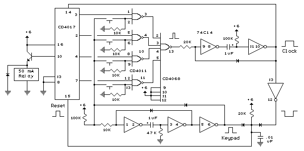
The digital lock shown below uses 4 common logic ICs to allow controlling a relay by entering a 4 digit number on a keypad. The first 4 outputs from the CD4017 decade counter (pins 3,2,4,7) are gated together with 4 digits from a keypad so that as the keys are depressed in the correct order, the counter will advance. As each correct key is pressed, a low level appears at the output of the dual NAND gate producing a high level at the output of the 8 input NAND at pin 13. The momentary high level from pin 13 activates a one shot circuit which applies an approximate 80 millisecond positive going pulse to the clock line (pin 14) of the decade counter which advances it one count on the rising edge. A second monostable, one shot circuit is used to generate an approximate 40 millisecond positive going pulse which is applied to the common point of the keypad so that the appropriate NAND gate will see two logic high levels when the correct key is pressed (one from the counter and the other from the key). The inverted clock pulse (negative going) at pin 12 of the 74C14 and the positive going keypad pulse at pin 6 are gated together using two diodes as an AND gate (shown in lower right corner). The output at the junction of the diodes will be positive in the event a wrong key is pressed and will reset the counter. When a correct key is pressed, outputs will be present from both monostable circuits (clock and keypad) causing the reset line to remain low and allowing the counter to advance. However, since the keypad pulse begins slightly before the clock, a 0.1uF capacitor is connected to the reset line to delay the reset until the inverted clock arrives. The values are not critical and various other timing schemes could be used but the clock signal should be slightly longer than the keypad pulse so that the clock signal can mask out the keypad and avoid resetting the counter in the event the clock pulse ends before the keypad pulse. The fifth output of the counter is on pin 10, so that after four correct key entries have been made, pin 10 will move to a high level and can be used to activate a relay, illuminate an LED, ect. At this point, the lock can be reset simply by pressing any key. The circuit can be extended with additional gates (one more CD4011) to accept up to a 8 digit code. The 4017 counting order is 3 2 4 7 10 1 5 6 9 11 so that the first 8 outputs are connected to the NAND gates and pin 9 would be used to drive the relay or light. The 4 additional NAND gate outputs would connect to the 4 remaining inputs of the CD4068 (pins 9,10,11,12). The circuit will operate from 3 to 12 volts on 4000 series CMOS but only 6 volts or less if 74HC parts are used. The circuit draws very little current (about 165 microamps) so it could be powered for several months on 4 AA batteries assuming only intermittent use of the relay.


Motion Sensor Light Switch


Motion Sensor Light Switch Circuit

Today many available commercial motion sensor light switches on the market, one of the brands that are sought after a Leviton motion sensor light switch type PR180-1LW Leviton decora Incandescent 500W, Passive Infrared Wall Switch Occupancy Sensor. You can buy it at a price of about $ 15. Motion sensors are widely used for home security, office, or the places that require extra security.
Motion sensor light switch is a human motion detector that works in a range of infrared detection. If the PIR sensor devices receive the infrared energy emitted by the human body, it will eventually be switching relay which in turn will turn on the lights. So the function of the use of this switch sensor for security purposes, particularly at nighttime conditions.
In addition to buying a human motion detector, if you want to do it yourself (DIY), a motion sensor switch, is now also widely available PIR sensor modules that are sold in general, so that by adding a high-gain amplifier which is equipped with a relay switch, then this it works as a motion sensor light switch.

Motion Sensor Light Switch Circuit Diagram

Here is a motion sensor light switch circuit is quite simple using the SB0061, the pyroelectric sensor module, developed to detect human body. A PIR detector combined with a Fresnel lens mounted on a compact with analog IC card (SB0061) and a limited part of the module. High-level output (3.3) pre-adjustable variable width (5secs -18 minutes) is provided.

PIR Motion Sensor Light Switch Circuit
PIR motion sensor light switch schematic on SB0061 presented here can be used for a security lighting or energy saving mode corridor. 12V DC required for the entire circuit can be powered by standard 12V AC adapter / battery.

Motion Sensor Light Switch Circuit – How It Works

Development of a simple motion sensor circuit and easy. When motion is detected at about 5-6 meters, or about 3.3 volts appears at the base of the transistor T1 and T2 to participate in the next relay driver transistor light. Therefore, the relay DPDT 12V to power the white LED current limit resistor R3. Spare relay contacts can be used as a switch controlling the external load correctly. White LED and relay will remain for a period of time depending on mono SB0061, 5 seconds to 18 minutes. Source: Motion Sensor Light Switch

Leaked Gas Detector

Description:


As shown by the gas sensor alarm QM, buck rectifier and regulator circuits, integrated circuits KD28, speaker Y and so on. QM gas sensor for the QM-N5 type. Step-down transformer rectifier and regulator circuit consists of B, the bridge's rectifier D1 ~ D4, C1, C2, integrated voltage regulator 7806 and so on.
Work, adjustment potentiometer W, the power for 1 minute. When the air is clean, QM corresponds to a larger resistance value, W the partial pressure is small, so that the KD28 reset the alarm does not occur. When a combustible gas when contact with QM, QM corresponds to the resistance value is small, W partial pressure on the larger, so KD28 set, the 3 foot high output speaker to promote the work of an alarm signal. Gas left the circuit will resume normal operation.


Digital Direction Compass

Circuit Diagram :


Direction :

Page Rank

google pagerank

Write For Us

Submit a Guest Post

Find us on Facebook

Categories

555 Timer IC 7 segment Display 8051 Project AC Circuits Adafruit Alarms Amplifier Circuits Analog Circuits android Arduino arm processor Assembly Languange Atmel Atom Size Audio Circuits augmented reality Automotive Circuits avr Battery Circuits Bicycle Gurad bluetooth Cable TV Circuits Cambridge University Camera Technology Circuit Boards Clipping And Clamping Circuits Clocking And Timer Circuits Computing contact lens Contact Us Form Contests Controller Circuit Conversion Circuits Counter Circuits Digital Electronics diy circuits Downloads EFY EFYTimes Electronic Books Electronic Components Electronic Locks And Keys Engineering Fan Circuits Filter Circuits Fire Alarm free Frequency Fun And Game Circuits future Google Hack n Mod Ham Radio Circuits heart rate monitoring High Voltage Circuits Home Circuits IC Guide ieee Industrial Circuits Infrared Instructables Inventions ipad lcd Led Circuits Light Related Lighting Circuits Medical Circuits Meter Clocks Microcontrollers Microprocessors Mini Projects modules Movie maker NatGeo Navigation Notice Optical Fiber PC Circuits PCB Boards Physics pnp transistor Power Supplies Printing Projects Programmer Project Ideas Projectors Protection circuits Proximity Detectors Radar Radio Circuits Radio Transmitters Raspberry Raspberry Pie Remote Circuits Retis Lab RFID Robot Cars Robotics Science Science Alert Security And Safety Sensor Circuits Servo Motors Smallest Smartwatches sms Software solar cell sound application Spectram Switch Technology News Telephone Related Television Related Test And Measurement Circuits Thermal Projects Tone generator circuits Touch Screen Tutorials Wearables Wi-Fi Wireless
Like us on Facebook
Follow us on Twitter
Recommend us on Google Plus
Subscribe me on RSS