Search This Blog

Powered by Blogger.

Translate

[TC] Physicists just built the world's smallest optical switch - based on a single atom


As our need for more data and faster transmissions grows, existing network infrastructure is being put under more strain than ever before. As a result, scientists are working hard to miniaturise these systems and switch from current electron-based computers to super-fast optics-based communications, where data is quite literally sent at the speed of light.
Now scientists working at ETH Zurich in Switzerland have made crucial progress in the design of a modulator - the device that converts electronic signals into optical ones. These devices are currently around 3 cm wide, which means when you have a data centre full of them, they take up a substantial amount of room. But this new modulator is based on an optical switch that uses just one atom.
As Gizmag's Colin Jeffrey reports, that's a level of miniaturisation that's surprised even the scientists themselves - it essentially allows light to pass through a gap that's smaller than the wavelength of light itself. A modulator built around this switch could be some 100,000 times smaller than the devices in use today.
Here's how it works: silver and platinum pads are placed on top of an optical waveguide made of silicon with just an atom's gap between them. Once voltage is applied to the silver pad, a single atom is drawn towards its furthermost point, closing up the gap and creating a circuit between the two pads. When voltage is removed, the atom retracts, and thus the modulator can transmit millions of switch signals every second.
But what about the physics-bending light compression? As the light is beamed across the waveguide, it gets converted into surface plasmon, made up of electrons that oscillate at the frequency of the laser light. These electrons can pass through the single atom gap before being reconverted on the other side. By reconfiguring the design of the modulator, the light is effectively squashed to squeeze through the gap.
"Until recently, even I thought it was impossible for us to undercut this limit,"said lead researcher, Jürg Leuthold. "This allows us to create a digital switch, as with a transistor. We have been looking for a solution like this for a long time."
Now the team wants to improve the modulator production process so it's suitable for large-scale use and reliable in operation - at the moment, only one out of every six attempts at fabrication is successful. Eventually, though, this single atom modulator could be helping to shift data around the planet faster than ever before.
Source: Science Alert

[TC] Heart rate monitor using 8051

This article is about a simple heart rate monitor using 8051 microcontroller. Like the previous 8051 projects, AT89S51 is the microcontroller used here. The device senses the heart rate from the finger tip using IR reflection method and displays it on a three digit seven segment display in beats per minute. The circuit has an accuracy of 4 beats per minute and it is very easy to use. In medical terms, the technique used here for sensing heart rate is called photoplethysmography.

Photoplethysmography.

Photoplethysmography is the process of optically estimating the volumetric measurement of an organ. Pulse oximetry, cardiovascular monitoring, respiration detection, heart rate monitoring etc are few common applications of photoplethysmography. Let us have a look at the application of photoplethysmography in heart rate monitoring from the figer tip. When the heart expands (diastole) the volume of blood inside the finger tip increases and when the heart contrcats (systole) the volume of blood inside the finger tip decreases. The resultant pulsing of blood volume inside the finger tip is directly proportional to the heart rate and if you could some how count the number of pulses in one minute, that’s the heart rate in beats per minute (bpm). For this an IR transmitter /receiver pair is placed in close contact to the finger tip. When the heart beats, the volume of blood cells under the sensor increases and this reflects more IR waves to sensor and when there is no beat the intensity of the reflected beam decreases. The pulsating reflection is converted to a suitable current or voltage pulse by the sensor. The sensor output is processed by suitable electronic circuits to obtain a visible indication (digital display or graph).

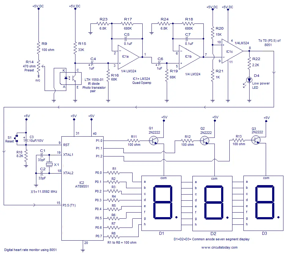
Heart rate monitor using 8051.

Circuit diagram.


Working of the heart rate monitor

LTH1550-01 photo interruptor forms the photoplethysmographic sensor here. LTH1550-01 is simply a IR diode – photo transistor pair in single package. The front side of the IR diode and photo transistor are exposed and the remaining parts are well isolated. When the finger tip is placed over the sensor the volumetric pulsing of  the blood volume inside the finger tip due to heart beat varies the intensity of the reflected beam and this variation in intensity is according to the heart beat.
When more light falls on the photo transistor it conducts more, its collector current increases and so its collector voltage decreases. When less light falls on the phototransistor it conducts less, its collector current decreases and so its collector voltage decreases. This variation in the collector voltage will be proportional to the heart rate. Any way this voltage variation is so feeble and additional signal conditioning stages are necessary to convert it into a microcontroller  recognizable form.
The next part of the circuit consists of a two active low pass filters using opampLM324.  The LM324 is a quad opamp that can be operated from a single rail supply. Resistor R23, R17 and capacitor C5 sets the gain and cut off frequency of the first filter. With the given component values, gain will be 101 and cut off frequency will be 2.5Hz. The gain and cut off frequency are determined using the following equations.
Voltage gain Av =1 + (R17 / R23)
Cut off frequency Fc= 1/(2π *R17*C5)
The second low pass filter also have the same parameters. The two low pass filters form a very critical part of the circuit as any noise or false signals passing to the microcontroller stage will produce disastrous results. The output of the filter stage will be a voltage level fluctuating between 0 and 0.35 volts and this fluctuation is converted into a 0 to 5V swing using the comparator  based on the third opamp (IC1c). The reference voltage of the comparator is set to 0.3V. When ever the output voltage of the filter stage goes above 0.3V, the output of the comparator goes to zero and whenever the output voltage of the filter stage goes below 0.3V, the output of the comparator goes to positive saturation. The result will be a neat pulse fluctuating between 0 and 5V at a rate equal to the heart rate. This pulse is fed to the microcontroller for counting.

Program.

ORG 000H // originMOV DPTR,#LUT // moves starting address of LUT to DPTRMOV P1,#00000000B // sets P1 as output portMOV P0,#00000000B // sets P0 as output portMAIN: MOV R6,#230D // loads register R6 with 230D SETB P3.5 // sets P3.5 as input port MOV TMOD,#01100001B // Sets Timer1 as Mode2 counter & Timer0 as Mode1 timer MOV TL1,#00000000B // loads TL1 with initial value MOV TH1,#00000000B // loads TH1 with initial value SETB TR1 // starts timer(counter) 1BACK: MOV TH0,#00000000B // loads initial value to TH0 MOV TL0,#00000000B // loads initial value to TL0 SETB TR0 // starts timer 0HERE: JNB TF0,HERE // checks for Timer 0 roll over CLR TR0 // stops Timer0 CLR TF0 // clears Timer Flag 0 DJNZ R6,BACK CLR TR1 // stops Timer(counter)1 CLR TF0 // clears Timer Flag 0 CLR TF1 // clears Timer Flag 1 ACALL DLOOP // Calls subroutine DLOOP for displaying the count SJMP MAIN // jumps back to the main loopDLOOP: MOV R5,#252DBACK1: MOV A,TL1 // loads the current count to the accumulator MOV B,#4D // loads register B with 4D MUL AB // Multiplies the TL1 count with 4 MOV B,#100D // loads register B with 100D DIV AB // isolates first digit of the count SETB P1.0 // display driver transistor Q1 ON ACALL DISPLAY // converts 1st digit to 7seg pattern MOV P0,A // puts the pattern to port 0 ACALL DELAY ACALL DELAY MOV A,B MOV B,#10D DIV AB // isolates the second digit of the count CLR P1.0 // display driver transistor Q1 OFF SETB P1.1 // display driver transistor Q2 ON ACALL DISPLAY // converts the 2nd digit to 7seg pattern MOV P0,A ACALL DELAY ACALL DELAY MOV A,B // moves the last digit of the count to accumulator CLR P1.1 // display driver transistor Q2 OFF SETB P1.2 // display driver transistor Q3 ON ACALL DISPLAY // converts 3rd digit to 7seg pattern MOV P0,A // puts the pattern to port 0 ACALL DELAY // calls 1ms delay ACALL DELAY CLR P1.2 DJNZ R5,BACK1 // repeats the subroutine DLOOP 100 times MOV P0,#11111111B RET DELAY: MOV R7,#250D // 1ms delay DEL1: DJNZ R7,DEL1 RET DISPLAY: MOVC A,@A+DPTR // gets 7seg digit drive pattern for current value in A CPL A RETLUT: DB 3FH // LUT starts here DB 06H DB 5BH DB 4FH DB 66H DB 6DH DB 7DH DB 07H DB 7FH DB 6FHEND

About the program.

For the counting purpose both the timers of 8051 (Timer0 and Timer1) are used. Timer 1 is configured as an 8 bit auto reload counter for registering the number of incoming zero going pulses and Timer0 is configured as a 16 bit timer which generate the necessary 1 second time span for the Timer1 to count.For counting the number of beats Timer0 and Timer1 are used. Timer1 is set as an 8 bit auto reload counter for counting the the number of pulses (indicating the heart beat) and Timer0 is set as a 16 bit timer which generates a 65536uS delay. When looped 230 times it will produce a 15 second time span (230 x 65536uS =15S)  for the Timer 1 to count. The number of counts obtained in 15 seconds is multiplied by 4 to obtain the heart rate in beats per minute.
 The Timer 0 which generates the 1 second time span is configured in Mode 1 (16 bit timer). So the maximum it can count is 2^16 and it is 65536. In 8051 the crystal frequency is divided by 12 using an internal frequency divider network before applying it as a clock for the timer. That means the timer will increment by one for every 1/12th of the crystal frequency. For an 8051 based system clocked by a 12MHz crystal, the time taken for one timer increment will be 1µS (ie; 1/12MHz). So the maximum time delay that can be obtained using one session of the timer will be 65536µS. Go through this article Delay using 8051 timer for a better grasp.
Setting up the circuit.
When power is switched ON, the indicator LED D4 will glow an continues in that state. Now place your finger tip over the sensor and adjust preset R14 so that the LED D4 starts blinking. After you got the LED blinking, reset the power and wait for 15 seconds. The display will show your heart rate in beats per minute.
Source: http://www.circuitstoday.com/heart-rate-monitor-using-8051

[TC] Building an analog meter clock with Atmel and Adafruit


“We wanted to design a microcontroller board that was small enough to fit into any project – and low cost enough to use without hesitation,” Adafruit’s Limor Fried (aka LadyAda) explained. “[It is] perfect for when you don’t want to give up your expensive dev-board and you aren’t willing to take apart the project you worked so hard to design.”
Although the Trinket launched in September, the ATtiny85-powered Trinket has already tipped up in a number of projects including a sound-reactive color LED organ, IR control device, Tap Tempo and a temperature/humidity sensor. Today, we’ll be talking about building a Trinket-powered analog meter clock. As Adafruit’s Mike Barela notes, the Trinket is a perfect fit for clock projects, as the platform is small and easy to hide behind a larger display.
“Clocks don’t need a lot of logic, this example only has maybe 20 lines of code, [while] adding a digital display via I2C is possible using seven segment or character-based displays (with the library code posted for other projects),” Barela wrote in a detailed tutorial on the subject. ”This [specific] project interfaces Trinket to the the Adafruit DS1307 real-time clock (RTC) breakout board to form a clock. But in a twist, the display is done using two analog meters. One for hours, one for minutes.”
According to Barela, the Trinket is capable of outputting to a meter without digital to analog converters.
“Trinket has pulse width modulation (PWM) on three of its pins. The meter uses a moving coil inductance movement, acting to average the indication of current flowing through it,” he continued.
“If you have narrow pulses, the average voltage it sees is lower, thus the current is lower for the fixed resistance attached to it. For wide pulses, the meter sees nearly the supply voltage and will stay around the full scale. This circuit varies the pulse width sent to the meters proportional to the hour of the day and the minutes after the hour.”
For two meters, says Barela, two of the three PWM pins on Trinket will be used (the third is also an I2C pin connected to the clock module). Although there are many ways to display the finished product, Adafruit decided to go with the meters “free-floating” in a colorful box, rather than a cabinet or plexiglass display.
To kick off the project, Barela recommends Makers first unpack their Trinket. Those using a breadboard or Perma-Proto board will want to solder on the (provided) header pins. After unpacking the DS1307 kit and building the circuit, Makers are instructed to modify the Arduino IDE to work with Trinket by adding the hardware definition file, the avrdude.conf file – while changing the ld.exe program from the 2008 dated version to the 2009 dated version and installing the driver for USBtinyISP appropriate to your operating system.
“To prepare the Trinket for other programs, you will want to first load the Trinket Blink sketch into the Arduino software then load it onto the Trinket to verify everything works well. You must press the hardware reset button on the Trinket then quickly press upload in the Arduino software to upload a sketch,” Barela added. “If you get an error, try the reset-upload process again. If you continually cannot load the blink sketch, check to make sure the Trinket is connected (without any wires connected to pins #3 and #4) and the Arduino IDE software has all the required changes.”'


Source: http://atmelcorporation.wordpress.com/2013/10/18/building-an-analog-meter-clock-with-atmel-and-adafruit/

Infrared Illuminator Made With LEDs

Figure:1

Figure 1 

As infrared LED array came up with technology and state of the art electronic and optical components that will bring us the ultimate in day and night vision efficiency and high power infrared output.
This can be started by calculating how much infrared radiation you will need in order to light your scene that would be the focal range of your camera since details are lost on most security cameras. With the use of Dremel tool or small bench top grinder, grind down one side of the LEDs slightly and then pack them down to a smaller area. The builder used 19 by 13 LEDs for a total of 247 LEDs, to fit into the inside of a halogen work light.
When the LED array is wired, simply run copper wire along the columns to create the parallel wiring connection for each series chain. The power adapter can be plugged into an AC socket just as it was before modification and cut the AC wiring inside the light enclosure and affixed it directly to the AC power adapter. Materials such as dark tinted glass will also work to conceal an LED array.

To see the rest of the project, go to <http://www.lucidscience.com/pro-led array illuminator-1.aspx>

Jet engine sound generator

Description.

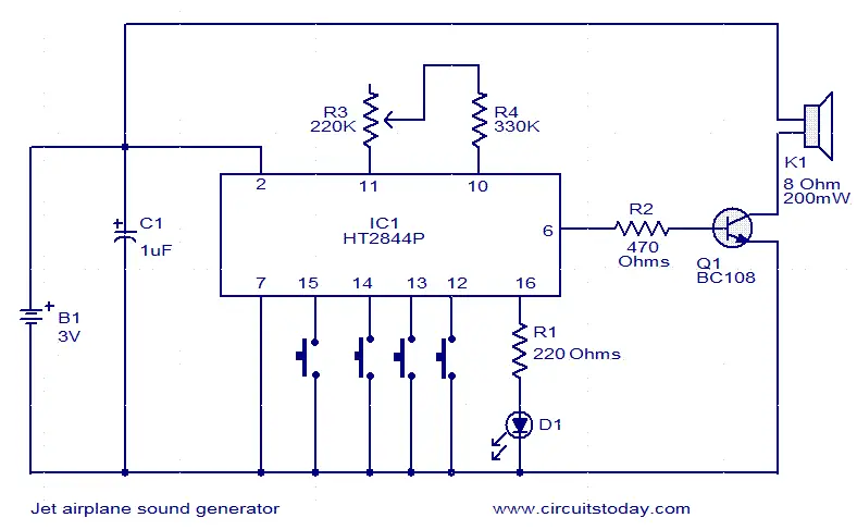
This jet engine sound generator circuit is based on the sound generator IC HT2844P from Holtek Semiconductors. This particular IC can make four sounds namely low speed sound of jet engine, high speed sound of jet engine, missile sound and machine gun sound. Each of these sounds can be activated by connecting the pins 12, 13, 14and 15 to ground by using the respective push button switches. Resistor R3 can be used for manually increasing or decreasing the speed.LED D1 gives a visible indication of the sound.
Circuit diagram.

jet-engine-sound-generator
Notes.
  • The circuit can be powered from a 3V battery.
  • Do not give more than 3.3V to the IC.
  • K1 can be a 200mW/8 Ohm speaker.
  • IC1 must be mounted on a holder.

CPU Monitoring Circuit


Excess heat too much can cause damage to the electronics. Similarly, on a computer or laptop, so monitor the temperature of CPU and other computer components are very important. 
In order for a laptop computer temperature monitoring program to function for most of this type, then you need to activate the ACPI BIOS motherboard. This program servesas a controller of the computer temperature monitor connected electronically to a temperature sensor and system protection. So it serves to monitor the circuit board, air, and the CPU temperature to protect the system from overheating.
Computer Temperature Monitor - Fan Cooling System
To provide an understanding and a global picture of thecomputer temperature monitor electronically, the following is examples of computer temperature monitor circuit that originates from the MAX6656 IC Application Note, A singletemperature sensor and voltage monitor IC can monitor temperatures in multiple locations.

MAX6656 Computer Temperature Monitor Circuit Diagram

The MAX6656 includes an on-chip “local” temperature sensor and can also measure the temperatures of two remote thermal diodes (either discrete or on the die of a device like a CPU or FPGA). In addition, the MAX6656′s voltage monitoring inputs can monitor the temperature of an external thermistor. The result is constant thermal monitoring of a board, die, and air temperature.
The computer temperature monitor circuit shown below protects a system from overheating by monitoring temperature in at least three locations using three different temperature measurement techniques. Thermal problems can be identified in three completely different environments; by measuring the temperature of a PCB, the die temperature of a CPU or other IC with a thermal sensing transistor, and chassis air. Monitoring PC board temperature helps to identify overheating of chips close to the sensor. Monitoring the die temperature of a CPU, FPGA, or other high-power chip that has an on-chip thermal monitoring diode can very quickly detect dangerous thermal conditions before an expensive device is damaged by heat. Air temperature can indicate such conditions as a failed or blocked cooling fan.
MAX6656 Computer Temperature Monitor Circuit Diagram

The computer temperature monitor circuit diagram shown above lets you measure and monitor CPU, circuit board, and ambient temperature. IC1 is a temperature and voltage monitor that continuously captures the temperature of two external thermal sense transistors, its own temperature, its supply voltage, and three external voltages. All measured quantities are compared against programmable temperature and voltage limits; if a value falls outside its limits, the ALERT pin asserts.  Please download MAX6656 Application Note (PDF) or visit MAX6656 Application Note page to read more about the information of computer temperature monitor.

Rain Detector Circuit

This circuit uses a sensor made of a small piece of etched PC board and a simple SCR circuit to detect rain and sound a buzzer. The SCR could also be used to activate a relay, turn on a lamp, or send a signal to a security system.


This is the schematic of the Rain Detector


Part


Total Qty.


Description


Substitutions
R1
1
1K 1/4 W Resistor
R2
1
680 Ohm 1/4 W Resistor
D1
1
1N4001 Silicon Diode
BZ1
1
12V Buzzer
S1
1
SPST Switch
SCR1
1
C106B1 SCR
106CY
SENSOR
1
See Notes
MISC
1
Board, Wire, Case, PC Board (For Sensor)

NOTE:
  1. The sensor is a small piece of PC board etched to the pattern showen in the schematic. The traces should be very close to each other, but never touching. A large spiral pattern would also work.
  2. Make sure to use a loud buzzer.

Leaked Gas Detector

Description:


As shown by the gas sensor alarm QM, buck rectifier and regulator circuits, integrated circuits KD28, speaker Y and so on. QM gas sensor for the QM-N5 type. Step-down transformer rectifier and regulator circuit consists of B, the bridge's rectifier D1 ~ D4, C1, C2, integrated voltage regulator 7806 and so on.
Work, adjustment potentiometer W, the power for 1 minute. When the air is clean, QM corresponds to a larger resistance value, W the partial pressure is small, so that the KD28 reset the alarm does not occur. When a combustible gas when contact with QM, QM corresponds to the resistance value is small, W partial pressure on the larger, so KD28 set, the 3 foot high output speaker to promote the work of an alarm signal. Gas left the circuit will resume normal operation.


AC Powered Blinking LED

I needed a pulsating light for a certain signaling. Voltage was 230V. So I decided to make a simple circuit, consisted of a LED diode, two capacitors, two resistors, a diac and a diode. Activity of the circuit is extraordinarily simple. The capacitor charges by the diode and the resistor. When the voltage on the capacitor achieves 30V the diac "releases" the electrical tension and the capacitor empties thorough the diac, LED blinks. Time base is dependent from the capacitor and the resistor, which is in series with diode 1N4007. Capacitor must be at least for 40V.

Circuit Diagram:


Practicle Diagram : 

Fridge Door Open Alarm

It beeps if the fridge door is left open for too long or hasn't closed properly, to stop food from spoiling. There are lots of other uses as well. A refrigerator or freezer door that is left open or ajar may cause the food contents to spoil. In some cases, the internal temperature of the fridge or freezer will be maintained if the refrigeration system can cope with the open door.

Complete project:


But without the door sealing in the cold air, it may be a losing battle. Running costs will certainly rise. Typically, refrigerators and freezers are in constant use in the summer months and so it is important to ensure that the door is not open for any longer than is necessary. Otherwise the fridge or freezer will not be able to keep the contents cool. And it will cost more money to needlessly run the fridge’s compressor in a futile effort to keep the contents cool.

Circuit looks like:


Even the most diligent fridge user may sometimes leave the door of the fridge or freezer open without realizing it. And tilting the fridge or freezer slightly backward so that the door will fall shut is not completely fool proof as there may be an obstruction inside the door. The obstruction could be because an item inside the compartment has moved or fallen over or because the compartment is too full. This is where the Fridge Alarm is useful.


It warns when the door of the refrigerator or freezer is left open for longer than a preset time period. It is great for indicating when someone is standing with the door open for too long and a real asset in warning when the door looks shut but is still partially ajar. The fridge alarm operates by detecting when any light enters the compartment area. Therefore it is just as useful for freezers (which normally do not have a light) as it is for fridges (which normally do). As long as there is some ambient light which the alarm can react to, it will operate.

Parts layout:


PCB layout:


Circuit diagram:


The alarm will sound if the light is present for longer than the preset period and will continue to sound until the door is closed. In practice, the preset period is adjusted so that in normal use the alarm will not sound. It will sound when the door is left wide open for too long or if left slightly ajar.

Note:

    You don't have to house it in a transparent box, as we did . . . but if you don't, you'll need another hole in the appropriate place on the box wall so light can strike the LDR inside.

UPDATE:

PCB layout has been added to download. Please click on the image below and get the PCB in EPS format. After downloading, you can view PCB in Corel Draw, Adobe Acrobat or Adobe Photoshop.

Page Rank

google pagerank

Write For Us

Submit a Guest Post

Find us on Facebook

Categories

555 Timer IC 7 segment Display 8051 Project AC Circuits Adafruit Alarms Amplifier Circuits Analog Circuits android Arduino arm processor Assembly Languange Atmel Atom Size Audio Circuits augmented reality Automotive Circuits avr Battery Circuits Bicycle Gurad bluetooth Cable TV Circuits Cambridge University Camera Technology Circuit Boards Clipping And Clamping Circuits Clocking And Timer Circuits Computing contact lens Contact Us Form Contests Controller Circuit Conversion Circuits Counter Circuits Digital Electronics diy circuits Downloads EFY EFYTimes Electronic Books Electronic Components Electronic Locks And Keys Engineering Fan Circuits Filter Circuits Fire Alarm free Frequency Fun And Game Circuits future Google Hack n Mod Ham Radio Circuits heart rate monitoring High Voltage Circuits Home Circuits IC Guide ieee Industrial Circuits Infrared Instructables Inventions ipad lcd Led Circuits Light Related Lighting Circuits Medical Circuits Meter Clocks Microcontrollers Microprocessors Mini Projects modules Movie maker NatGeo Navigation Notice Optical Fiber PC Circuits PCB Boards Physics pnp transistor Power Supplies Printing Projects Programmer Project Ideas Projectors Protection circuits Proximity Detectors Radar Radio Circuits Radio Transmitters Raspberry Raspberry Pie Remote Circuits Retis Lab RFID Robot Cars Robotics Science Science Alert Security And Safety Sensor Circuits Servo Motors Smallest Smartwatches sms Software solar cell sound application Spectram Switch Technology News Telephone Related Television Related Test And Measurement Circuits Thermal Projects Tone generator circuits Touch Screen Tutorials Wearables Wi-Fi Wireless
Like us on Facebook
Follow us on Twitter
Recommend us on Google Plus
Subscribe me on RSS