Search This Blog

Powered by Blogger.

Translate

There's a 'Desert' in The Middle of The Pacific. Here's What Lives There

In the centre of the South Pacific, there's a place as far away from land as anyone on Earth could ever hope to get. The ocean is different there.

These distant waters lie at the heart of the South Pacific Gyre, the centre of which holds the 'oceanic pole of inaccessibility': the ocean's remotest extreme, aka Point Nemo (a name meaning 'no-one'), famous otherwise for being a spacecraft cemetery.

But aside from the ghosts of burnt-up satellites, what dwells under these far-off waves?

Not much, scientists have long thought. Despite taking up 10 percent of the ocean's surface, the South Pacific Gyre (SPG) – the largest of Earth's five giant ocean-spanning current systems – is generally considered a 'desert' in terms of marine biology.

Nonetheless, stuff does live there, even if organic life in these waters (and the seabed below it) is few and far between, due to a range of factors.

These include distance from land (and the nutrient matter it provides), the way water swirling currents isolate the centre of the gyre from the rest of the ocean, and high UV levels in this part of the ocean.

In truth, though, we don't actually know all that much about the life-forms that inhabit the SPG, largely because of how hard it is to study this oceanic desert – due to both its extreme remoteness, and also how large it is, covering about 37 million square kilometres (14 million square miles).

Despite the challenges, a recent international research effort has given us what the scientists claim is an unparalleled glimpse at the microbial creatures that exist in these waters.

During a six-week expedition aboard the German research vessel FS Sonne from December 2015 to January 2016, a crew led by the Max Planck Institute for Marine Microbiology sailed a 7,000-kilometre (4,350 miles) journey through the SPG from Chile to New Zealand.

En route, they sampled the microbial populations of the remote waters at depths between 20 to 5,000 metres (65 ft to 16,400 ft), using a newly developed analysis system that enabled the researchers to sequence and identify organic samples en route in as little as 35 hours.
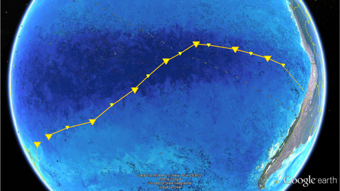
016 south pacific gyre 1 (Max Planck Institute for Marine Microbiology/Google Earth/NASA)

Above: FS Sonne's path crossing the SPG from Chile to New Zealand.

"To our surprise, we found about a third less cells in South Pacific surface waters compared to ocean gyres in the Atlantic", said one of the researchers, microbial ecologist Bernhard Fuchs, back in July 2019.

"It was probably the lowest cell numbers ever measured in oceanic surface waters."

Among the microbes the team found, 20 major bacterial clades dominated the lot. These were mostly organisms scientists have encountered in other gyre systems, such as SAR11, SAR116, SAR86, Prochlorococcus, and more.

The distribution of these microbe communities depended largely on water depth, based around factors such as changes in temperature, nutrient concentrations, and availability of light.

One of the populations identified, called AEGEAN–169, was particularly numerous in the surface waters of the SPG, whereas previous research had only discovered them at 500-metre depths.

"This indicates an interesting potential adaptation to ultraoligotrophic [low in biological productivity] waters and high solar irradiance", said one of the team, microbiologist Greta Reintjes.

"It is definitely something we will investigate further."

On the whole though, the sampling generally confirmed that the SPG is a "unique, ultraoligotrophic habitat", where low nutrient availability restricts growth to specialist oligotrophic organisms and creatures that have adapted to "extreme physicochemical conditions".

In other words, the SPG can't shake off its 'desert' reputation just yet, but there is a bright side to all that organic absence: these distant, almost lifeless waters are said to be the clearest ocean in all the world.

The findings were reported in Environmental Microbiology.

A version of this article was first published in July 2019.


Source: https://www.sciencealert.com

[TC] Control your PC with TV Remote

Now you can control your mouse cursor and windows media player with your TV remote… So when you are watching a movie or listening songs on your PC, you need not to get up from your seat to change the volume or to change the track.. you can simply use your TV remote to do this.
Description:
This project is an implementation of RC5-remote reception on an 8051 microcontroller. The received code is decoded and sent to the PC IR remote software written in Visual Basic. The cursor position is moved according to the keys pressed.
There are two modes of operation one is as mouse control and second is Windows media player control. More information on key control is given in the software’s help section. You might need to download the VB library files to run this software.
Circuit diagram Control your PC with TV Remote
View video of the project:


[youtube=http://www.youtube.com/v/VCWyQzs0E98]
VB program of Control your PC with TV Remote
Download the project by  clicking here
If the software gives an error of missing file “MSCOMM32.ocx”, the use the ocx file supplied in the zip file and follow the instructions below:
1. Copy MSCOMM32.ocx in “c:\windows\system” folder.2. Go to Start -> run and type “regsvr32 mscomm32.ocx” and hit enter. It will give you a success dialog.
Source: http://electrofriends.com/

[TC] Remote controlled Spy Bot

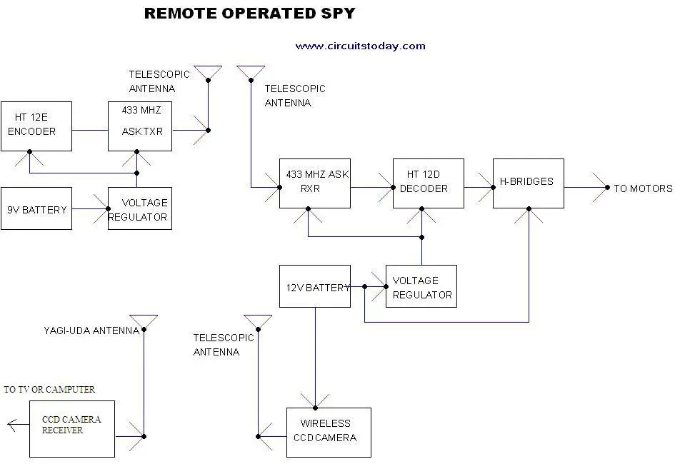
Here is a remote operated spy robot circuit which can be controlled by using a wireless remote controller. It can capture audio and video information’s from the surroundings and can be sent to a remote station through RF signals. The maximum range is 125 meters. It overcomes the limited range of infrared remote controllers. This robot consists of mainly two sections. They are explained in detail below.

Remote Control Operated Spy Robot Circuit – Block Diagram

    Remote Control Operated Spy Robot Circuit - Block Diagram
Remote Control Operated Spy Robot Circuit - Block Diagram

1. Remote Control Section

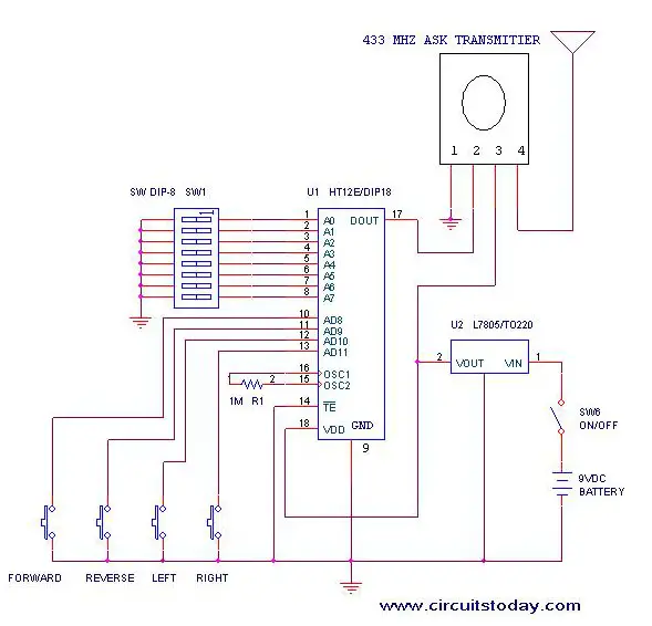
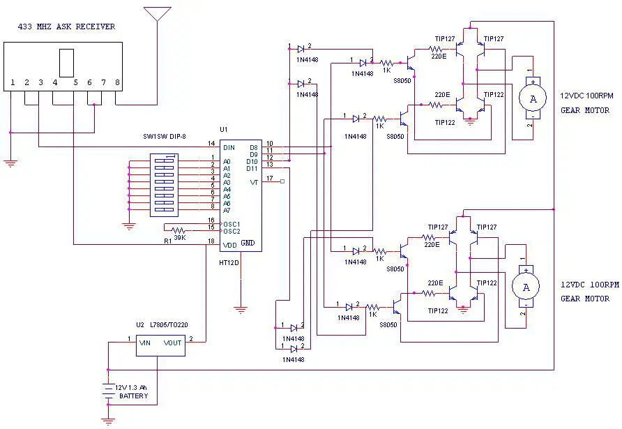
The circuit uses HT 12E, HT 12D encoder and decoder. 433MHz ASK transmitter and receiver is used for the remote control. H-bridge circuits are used for driving motors. Two 12V DC/100RPM gear motors are used as drivers. The working of the circuit is as follows.
When we are pressing any key in remote controller the HT 12E generate 8 bit address and 4 bit data .The DIP switches are used for setting the address. Then the ASK transmitter sends the 8 bit address and 4 bit data to the receiver Then the ASK receiver receives the 8 bit address and 4 bit data and HT 12D decoder decodes the data, thus enabling the appropriate output. Thus the output signals that are generated controls the H-bridge which then rotates the motors.
The 433 MHZ ASK transmitter and receivers are extremely small, and are excellent for applications requiring short-range RF remote controls.  The transmitter module is only 1/3rd the size of a standard postage stamp, and can easily be placed inside a small plastic enclosure. The transmitter output is up to 8mW at 433.92MHz. The transmitter accepts both linear and digital inputs and can operate from 1.5 to 12 Volts-DC, and makes building a miniature hand-held RF transmitter very easy.  The 433 MHZ ASK transmitters is approximately the size of a standard postage stamp
433 MHZ ASK receivers also operate at 433.92MHz, and have a sensitivity of 3uV.  The receiver operates from 4.5 to 5.5 volts-DC.
Remote-Control-Operated-Spy-Robot-Circuit-Remote-Control-Section

2. Video Transmission Section

In this project we are using a wireless CCD camera. Now these types of cameras are commonly available in the market. It works on 12VDC supply.


The 12 Volt DC supply is taken from the battery placed in the robot. The camera has a receiver, which is placed in the remote station. Its output signals are in the form of audio and video. These signals are directly connected to a TV receiver or a computer through a tuner card.
Remote Operated Spy Robot - Remote Control Section

Components Required

IC HT 12E 1
HT 12D 1

LM 7805 2
TRANSISTOR TIP 127 4

TIP 122 4

S 8050 4
DIODE 1N 4148 8
RESISTOR 1K 4

220E 4

39K 1

1M 1
ASK TRANSMITTER 433 MHz 1
ASK RECEIVER 433 MHz 1
DIP SWITCH
2
PUSH TO ON SWITCH
4
GEAR MOTOR 12V DC 100rpm 2
BATTERY 12V 1.3 Ah   rechargeable 1

9V 1
WIRELESS CCD CAMERA
1

Construction

The steps for the construction are…
1. Take a hylam sheet with (20cm*15cm) size.
2. Fix two gear motors (12VDC 100rpm) in the hylam sheet by using aluminum pieces and nut bolts as shown in the figure below.
3. Fix the ball castor as shown in the figure below.
Construction of Remote Operated Spy Robot Circuit
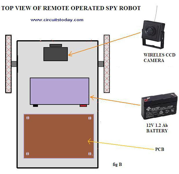
4. Then fix the battery (12VDC 1.2Ah) on the top of the spy robot as shown in the figure below.
Construction of Remote Operated Spy Robot Circuit - Top View
Construction of Remote Operated Spy Robot Circuit – Top View
5. Connect two motors to the PCB. The PCB is then connected to the battery.
6. Connect the wireless CCD camera to the battery.
7. Connect the camera receiver to the TV or computer. Video information’s will thus appear in the screen.
8. Switch on the remote controller and control the spy robot


Source: http://www.circuitstoday.com/

[TC] ExpeditInvaders Shelf -Arduino Based LED Lighting Shelf


Currently ExpeditInvaders support 10 color sets (RGB, Rasta, CGA, Brazil, Fizz, Kitty, Neon, Lantern, Lemming, LeBron) and 6 animation modes (Random, Solid, Ordered, Checkboard, Weird, Weirdtwo). The best thing about ExpeditInvaders is, that you can use your feets to change the color set or animation mode. Under the shelf is a PS2 keyboard attached. The keyboard has a special key map installed, if a key on the left side is pressed the color set change, if a key on the right side is pressed the animation will change.
If you press ESC + Arrow Right ExpeditInvaders will save the current state to the EEPROM. This state will be restored next time ExpeditInvaders is restarted.

All you need to spice up your Expedit Shelf are two strands of LED modules, an Arduino board (doesn’t matter which one, can be an old Duemilanove or a new Leonardo) and an old PS2 Keyboard.

Step 1, align LED Modules
Align the modules like on this image (back view):

It should look like this, once you installed them:


Step 2: Connect Devices to Arduino
Connect Pin 13 to LED Module Clock, Pin 11 to LED Module Data and GND to LED Module GND.
Connect 5v and GND to the PS2 Module, Connect Data to Pin 2 and Clock to Pin 3.

You can use an Arduino without pinheaders (solder direct on the board) or you use a ProtoShield Kit.

Here is the PS2 connection schema (thanks to prjc.com, I ripped your image):


Step 3: (Hot) Glue keyboard under the shelf
Just hot glue the keyboard under the shelf, make sure the cable is correct aligned. Now you can kick your Arduino Project…


Step 4: Upload Firmware to Arduino
Get the ExpeditInvaders Firmware on my GitHub repo and upload it to your Arduino board.


Step 5: Connect 12V to the Arduino and LED Modules
Connect 12V to the Arduino and LED Modules. You can use an old ATX power supply or a new 12V/24Watt Power supply.


ANd You Are Done!
Links

More Images


SMS Remote Control For Ericsson T10s Cell Phone


SMS Remote Control For Ericsson T10s Cell Phone


Digital Microwave Communications


Microwave is a kind of electromagnetic wave. In a broad sense, the microwave frequency range is from 300 MHz to 300 GHz. But In microwave communication, the frequency range is generally from 3 GHz to 30 GHz.


Concept of Digital Microwave Communication

Digital microwave communication is a way of transmitting digital information in atmosphere through microwave or radio frequency (RF).

Microwave communication refers to the communication that use microwave as carrier.

Digital microwave communication refers to the microwave communication that adopts the digital modulation.

The baseband signal is modulated to intermediate frequency (IF) first . Then the intermediate frequency is converted into the microwave frequency.

The baseband signal can also be modulated directly to microwave frequency, but only phase shift keying (PSK) modulation method is applicable.


Src:Here

Low Cost Water Pump Controller circuit


Here the circuit diagram of low cost water pump controller. The automatic pump controller minimizes the need for any manual switching of water pumps installed for the functionality of pumping water from a reservoir to an overhead tank . It instantly switches on the pump once the water level within the tank falls below a specific low level (L), provided the water level in the reservoir is above a specific level (R). Subsequently, because the water level in the tank increases to an upper level (M), the pump is turned off instantly. The pump is turned on again only if the water level once again falls beneath level L in the tank, provided the level inside the reservoir is above R. This automated action
continues.


The circuit is intended to ‘overlook’ the transient oscillations of the water level that would otherwise trigger the logic to modify its state rapidly and unnecessarily. The circuit works by using a single CMOS chip (CD4001) for logic processing.
No utilization of any moving electromechanical elements within the water-level sensor has been made. This assures fast reaction, no wear and tear, and no mechanical problems. The circuit diagram can be seen on above image. The unit performed satisfactorily on a test run in conjunction with a 0.5 HP motor and pump.
The sensors applied to the circuit could be any two conducting probes, preferably resistant to electrolytic corrosion. For example, in the easiest case, a appropriately sealed audio jack could be utilized to operate as the sensor.
Low Cost Water Pump Controller circuit
The circuit may also be utilized like a constant fluid level maintainer. For this objective, the probes M and L are brought pretty near to one another to make sure that the fluid level is maintained within the M and L levels.
The benefit of this system is that it could be applied to tanks/reservoirs of any volume whatsoever. Even so, the circuit can’t be applied for purely non-conducting fluids. For non-conducting fluids, some modifications have to be prepared in the fluidlevel sensors. The circuit can on the other hand be kept intact.

Page Rank

google pagerank

Write For Us

Submit a Guest Post

Find us on Facebook

Categories

555 Timer IC 7 segment Display 8051 Project AC Circuits Adafruit Alarms Amplifier Circuits Analog Circuits android Arduino arm processor Assembly Languange Atmel Atom Size Audio Circuits augmented reality Automotive Circuits avr Battery Circuits Bicycle Gurad bluetooth Cable TV Circuits Cambridge University Camera Technology Circuit Boards Clipping And Clamping Circuits Clocking And Timer Circuits Computing contact lens Contact Us Form Contests Controller Circuit Conversion Circuits Counter Circuits Digital Electronics diy circuits Downloads EFY EFYTimes Electronic Books Electronic Components Electronic Locks And Keys Engineering Fan Circuits Filter Circuits Fire Alarm free Frequency Fun And Game Circuits future Google Hack n Mod Ham Radio Circuits heart rate monitoring High Voltage Circuits Home Circuits IC Guide ieee Industrial Circuits Infrared Instructables Inventions ipad lcd Led Circuits Light Related Lighting Circuits Medical Circuits Meter Clocks Microcontrollers Microprocessors Mini Projects modules Movie maker NatGeo Navigation Notice Optical Fiber PC Circuits PCB Boards Physics pnp transistor Power Supplies Printing Projects Programmer Project Ideas Projectors Protection circuits Proximity Detectors Radar Radio Circuits Radio Transmitters Raspberry Raspberry Pie Remote Circuits Retis Lab RFID Robot Cars Robotics Science Science Alert Security And Safety Sensor Circuits Servo Motors Smallest Smartwatches sms Software solar cell sound application Spectram Switch Technology News Telephone Related Television Related Test And Measurement Circuits Thermal Projects Tone generator circuits Touch Screen Tutorials Wearables Wi-Fi Wireless
Like us on Facebook
Follow us on Twitter
Recommend us on Google Plus
Subscribe me on RSS