Search This Blog

Powered by Blogger.

Translate

There's a 'Desert' in The Middle of The Pacific. Here's What Lives There

In the centre of the South Pacific, there's a place as far away from land as anyone on Earth could ever hope to get. The ocean is different there.

These distant waters lie at the heart of the South Pacific Gyre, the centre of which holds the 'oceanic pole of inaccessibility': the ocean's remotest extreme, aka Point Nemo (a name meaning 'no-one'), famous otherwise for being a spacecraft cemetery.

But aside from the ghosts of burnt-up satellites, what dwells under these far-off waves?

Not much, scientists have long thought. Despite taking up 10 percent of the ocean's surface, the South Pacific Gyre (SPG) – the largest of Earth's five giant ocean-spanning current systems – is generally considered a 'desert' in terms of marine biology.

Nonetheless, stuff does live there, even if organic life in these waters (and the seabed below it) is few and far between, due to a range of factors.

These include distance from land (and the nutrient matter it provides), the way water swirling currents isolate the centre of the gyre from the rest of the ocean, and high UV levels in this part of the ocean.

In truth, though, we don't actually know all that much about the life-forms that inhabit the SPG, largely because of how hard it is to study this oceanic desert – due to both its extreme remoteness, and also how large it is, covering about 37 million square kilometres (14 million square miles).

Despite the challenges, a recent international research effort has given us what the scientists claim is an unparalleled glimpse at the microbial creatures that exist in these waters.

During a six-week expedition aboard the German research vessel FS Sonne from December 2015 to January 2016, a crew led by the Max Planck Institute for Marine Microbiology sailed a 7,000-kilometre (4,350 miles) journey through the SPG from Chile to New Zealand.

En route, they sampled the microbial populations of the remote waters at depths between 20 to 5,000 metres (65 ft to 16,400 ft), using a newly developed analysis system that enabled the researchers to sequence and identify organic samples en route in as little as 35 hours.

016 south pacific gyre 1 (Max Planck Institute for Marine Microbiology/Google Earth/NASA)

Above: FS Sonne's path crossing the SPG from Chile to New Zealand.

"To our surprise, we found about a third less cells in South Pacific surface waters compared to ocean gyres in the Atlantic", said one of the researchers, microbial ecologist Bernhard Fuchs, back in July 2019.

"It was probably the lowest cell numbers ever measured in oceanic surface waters."

Among the microbes the team found, 20 major bacterial clades dominated the lot. These were mostly organisms scientists have encountered in other gyre systems, such as SAR11, SAR116, SAR86, Prochlorococcus, and more.

The distribution of these microbe communities depended largely on water depth, based around factors such as changes in temperature, nutrient concentrations, and availability of light.

One of the populations identified, called AEGEAN–169, was particularly numerous in the surface waters of the SPG, whereas previous research had only discovered them at 500-metre depths.

"This indicates an interesting potential adaptation to ultraoligotrophic [low in biological productivity] waters and high solar irradiance", said one of the team, microbiologist Greta Reintjes.

"It is definitely something we will investigate further."

On the whole though, the sampling generally confirmed that the SPG is a "unique, ultraoligotrophic habitat", where low nutrient availability restricts growth to specialist oligotrophic organisms and creatures that have adapted to "extreme physicochemical conditions".

In other words, the SPG can't shake off its 'desert' reputation just yet, but there is a bright side to all that organic absence: these distant, almost lifeless waters are said to be the clearest ocean in all the world.

The findings were reported in Environmental Microbiology.

A version of this article was first published in July 2019.


Source: https://www.sciencealert.com

[TC] Physicists just built the world's smallest optical switch - based on a single atom


As our need for more data and faster transmissions grows, existing network infrastructure is being put under more strain than ever before. As a result, scientists are working hard to miniaturise these systems and switch from current electron-based computers to super-fast optics-based communications, where data is quite literally sent at the speed of light.
Now scientists working at ETH Zurich in Switzerland have made crucial progress in the design of a modulator - the device that converts electronic signals into optical ones. These devices are currently around 3 cm wide, which means when you have a data centre full of them, they take up a substantial amount of room. But this new modulator is based on an optical switch that uses just one atom.
As Gizmag's Colin Jeffrey reports, that's a level of miniaturisation that's surprised even the scientists themselves - it essentially allows light to pass through a gap that's smaller than the wavelength of light itself. A modulator built around this switch could be some 100,000 times smaller than the devices in use today.
Here's how it works: silver and platinum pads are placed on top of an optical waveguide made of silicon with just an atom's gap between them. Once voltage is applied to the silver pad, a single atom is drawn towards its furthermost point, closing up the gap and creating a circuit between the two pads. When voltage is removed, the atom retracts, and thus the modulator can transmit millions of switch signals every second.
But what about the physics-bending light compression? As the light is beamed across the waveguide, it gets converted into surface plasmon, made up of electrons that oscillate at the frequency of the laser light. These electrons can pass through the single atom gap before being reconverted on the other side. By reconfiguring the design of the modulator, the light is effectively squashed to squeeze through the gap.
"Until recently, even I thought it was impossible for us to undercut this limit,"said lead researcher, Jürg Leuthold. "This allows us to create a digital switch, as with a transistor. We have been looking for a solution like this for a long time."
Now the team wants to improve the modulator production process so it's suitable for large-scale use and reliable in operation - at the moment, only one out of every six attempts at fabrication is successful. Eventually, though, this single atom modulator could be helping to shift data around the planet faster than ever before.
Source: Science Alert

[TC] Arduino Video Game for the Neighbourhood update 2014


My house/office has a store window and I try to make use of it as much as possible. I had some projections etc. in there before, but now I wanted to make something interactive. We have a lot of loitering youth and many people passing by. To appeal to a wide audience, I thought it would be nice to make an old fashion arcade box like thing.
It’s now on the street for one day and people really seem to like it. Age or background doesn’t make a difference.
To make it a little bit more challenging,  I thought it would be fun to try to run the hole thing on an Arduino without an external computer. Just to see how much power it actually has. And while I was at it, I decided to try to make everything myself. So I also made my own led screen, with his own “display driver” and display list, a 8-bit sound library, and of course the game itself.
The only thing I didn’t make was the background music for the game, that was composed by the lovely Annegreet Sledsens: Thanks sweety!  You can hear it in the video.
The led screen is very bright which made it very hard to film and photograph with my cheap camera. Even after some photoshopping, I couldn’t  make it look as good as in real life. So if you’re in the neighbourhood (Antwerp Belgium, Provinciestraat 60, behind the Zoo), feel free to come check it out and play a game with the locals!
Here the video and some more pics:


The Game


I needed something that would appeal to a large audience (the people in my street) and something was fun to play .
So I took the good old gaming cliché, where the world gets invaded by aliens and you have to fight your way to the end boss, save the world and the human race . With my minimal resolution of 16*90 pixels, I didn’t have much other choice than making it pixel-art style.

The game has 3 modes, a single-player and a multiplayer brawling/fighting the aliens mode, and an extra fighting mode where the 2 players can battle with each other.
Every mode has just one level, but since it is just a casual “play on your way to work” kind of game, I thought it would be more then ok.
some screen-shots:

The game-mode selection:

Two players fighting the the final boss:

The girl kicking the boys ass in fighting mode:

Game over!


Development


To make the development easy and fast, I cross developed the game as a Cinder c++ app  and an Arduino app, that way i didn’t had to upload the whole thing on an Arduino every time I wanted to test something.

I didn’t use any external memory, so I had to store everything on the Arduino.  I made a small app that generates c++ classes from bitmaps with some gamma correction for the led screen. I used indexed colours to save some of that precious SRAM. For driving the leds, I modified the Adafruit neopixel lib, to support alpha-blending and make it a little bit faster for my specific case.
I don’t really have much experience with generating sound and music. So the 8-bit sound was quite challenging. I’m happy with the result, but my oscilloscope broke during development of a more advanced sound lib, so its quite simple for now. But I really enjoyed  myself working on the sound aspect. I have a feeling that my next project is going to be something sound/music related ;)
I’m not going to elaborate too much on the rest of the code. But you’re free to check the source code yourself  (warning: its messy).
The full source code and game assets on Github (Code-> MIT, Assets-> CC attribution)

The Hardware


Like I said, I made my own led display.

I used strips of  WS2812 LEDs, those are individually-addressable RGB LEDs. The lay in a 16*90 grid (=1440 leds)
I added a laser cut raster over the leds to make the pixels square and put a layer of plexi to diffuse the light some more.

Beneath the leds is the main Arduino Due and the power source. This is the Arduino that drives the display and runs the game. Those leds suck a lot of power , so I had to add a 60A 5V power supply.

The screen/main arduino is connected with the arcade box through a simple tx-rx serial line, which was fast enough to send the button commands.
the arcade box is just some painted MDF with a steel frame inside, and a steel plate on-top (it has to be a little bit solid if i leave it outside ;) )
The Arduino in the arcade box generates the sound and music and handles the raw button/joystick input.


If your interested,  the full “schematic” of the project:
Its pretty straight forward.: Pulldowns for the buttons and joystick, the led connections and a pot for the screen brightness and a tx-rx line between the two Arduinos.
on top of that there is a DC coupling for the speaker which is connected to the Arduino DAC . But I still have to put some kind of amplifier between the arduino and the speakers. The sound is hard to hear because of the street noise.


[TC] Water Level Indicator with Alarm using 8051 Micro controller (AT89C51)

This article illustrates the construction and working of a liquid/water level indicator. Such an indicator is used in tanks to indicate the level of liquids and alert us when the tank is full. So by this circuit we can monitor the various levels of the tank and can avoid spillage of water and also we can configure our supplies according to the various levels of tank. Such module or circuit can be installed in big buildings where manual monitor of tanks is difficult and its indicator can be placed at some centralized place.


This water level indicator circuit works on the principle that water conducts electricity. A wire connected to VCC and four other wires are dipped in tank at different levels namely quarter, half, three-fourth, full and their output are taken on pins P3.0, P3.1, P3.2, P3.3 via a transistor BC547. Port P2 is connected to data pins of LCD and P1.0, P1.1, P1.2 are respectively connected to RS, RW, and EN pins of LCD.

Initially when the tank is empty LCD will show the message VACANT. As the tank starts filling up wire at different levels get some positive voltage, due to conducting nature of water. This voltage is then fed to their corresponding pins on controller. When level reaches to quarter level, LCD displays the messageQUARTER. On further rise of level, HALF and 3/4 QUARTER are displayed on LCD. When tank gets full LCD shows the message FULL CLOSE TAP. A buzzer is also provided to produce a alert the user when the tank gets filled. This buzzer can be made off by pressing the switch connected between pin 15 of controller and VCC.
Circuit Diagram :


CODE
// Program to make a Liquid level indicator using LCD
#include<reg51.h>
sbit rs=P1^0; //register select pin
sbit rw=P1^1; //read/write pin
sbit e=P1^2; //enable pin
sbit quat=P3^0; //pin connected to quater level of tank
sbit half=P3^1; //pin connected to half level of tank
sbit quat_3=P3^2; //pin connected to three -fourth level of tank
sbit full=P3^3; //pin connected to full level of tank
sbit spkr_on=P3^4;  
sbit spkr_off=P3^5; // pin to off speaker

void delay(int k) //delay function
{
int i,j;
for(i=0;i<k;i++)
  for(j=0;j<1275;j++);
}

void write(int j) //write function
{
rs=1;  //selecting command register
rw=0;  //selecting to write
P2=j;  //putting value on the pins
e=1;  //strobe the enable pin
delay(1);
e=0;
return;
}

void cmd(int j)  //command function
{
P2=j;  //put the value on pins
rs=0;  //selecting command register
rw=0;  //selecting to write
e=1;  //strobe enable pin
delay(1);
e=0;
return;
}

void puts(char *a) //puts function to print a string
{
unsigned int p=0;
for(;a[p]!=0;p++)
write(a[p]);
}

void lcd_init(void) // function to initialise the LCD
{
cmd(0x38); //setting 8-bit interface, 2 lines, 5*7 Pixels
delay(1);
cmd(0x0e); //turning on underline visible cursor
delay(1);     
cmd(0x01); //clearing screen
cmd(0x80); //moving cursor to the begining of line 1 of LCD
}

void main()
{
quat=half=quat_3=full=spkr_off=1; //configuring as input pins
quat=half=quat_3=full=spkr_off=0; //lowering input pins
spkr_on=1;    // making speaker on pin high,as it works on negative logic
while(1)
{
  while(quat==0&&half==0&&quat_3==0&&full==0&&spkr_off==0)   //condition when tank is empty
  {
   lcd_init();        // initialising LCD
   puts("VACANT");       //printing VACANT on lcd
  }
  while(quat==1&&half==0&&quat_3==0&&full==0&&spkr_off==0)	//condition when tank is quater
  {
   lcd_init();
   puts("QUATER");      //printing QUATER on lcd
  }
  while(quat==1&&half==1&&quat_3==0&&full==0&&spkr_off==0)	//condition when tank is half
  {
   lcd_init();     
   puts("HALF");      //printing HALF on lcd
  }
  while(quat==1&&half==1&&quat_3==1&&full==0&&spkr_off==0)	//condition when tank is three-fourth
  {
   lcd_init();
   puts("3/4 FULL");     //printing 3/4 FULL on lcd
  }
  while(quat==1&&half==1&&quat_3==1&&full==1&&spkr_off==0)	//condition when tank is full
  {
   lcd_init();
   puts("FULL;CLOSE TAP");     //printing FULL;CLOSE TAP on lcd
   spkr_on=0;// Enabling speaker
  }
  while(quat==1&&half==1&&quat_3==1&&full==1&&spkr_on==0&&spkr_off==1)//enabling high speaker_off pin
  {
   spkr_on=1;//disabling speaker
  }
}
}


[TC] Automatic Street Light

Introduction:
Needs no manual operation for switching ON and OFF. When there is need of light it automatically switches ON. When darkness rises to a certain value then sensor circuit gets activated and switches ON and when there is other source of light i.e. day time, the street light gets OFF. The sensitiveness of the street light can also be adjusted. In our project we have used four L.E.D for indication of bulb but for high power switching one can connect Relay (electromagnetic switch) at the output of pin 3 of I.C 555. Then it will be possible to turn ON/OFF any electrical appliances connected all the way through relay.

                        Automatic Street Light
Principle :
This circuit uses a popular timer I.C 555. I.C 555 is connected as comparator with pin-6 connected with positive rail, the output goes high(1) when the trigger pin 2 is at lower then 1/3rd level of the supply voltage. Conversely the output goes low (0) when it is above 1/3rd level. So small change in the voltage of pin-2 is enough to change the level of output (pin-3) from 1 to 0 and 0 to 1. The output has only two states high and low and can not remain in any intermediate stage. It is powered by a 6V battery for portable use. The circuit is economic in power consumption. Pin 4, 6 and 8 is connected to the positive supply and pin 1 is grounded. To detect the present of an object we have used LDR and a source of light. LDR is a special type of resistance whose value depends on the brightness of the light which is falling on it. It has resistance of about 1 mega ohm when in total darkness, but a resistance of only about 5k ohms when brightness illuminated. It responds to a large part of light spectrum. We have made a potential divider circuit with LDR and 100K variable resistance connected in series. We know that voltage is directly proportional to conductance so more voltage we will get from this divider when LDR is getting light and low voltage in darkness. This divided voltage is given to pin 2 of IC 555. Variable resistance is so adjusted that it crosses potential of 1/3rd in brightness and fall below 1/3rd in darkness.
Sensitiveness can be adjusted by this variable resistance. As soon as LDR gets dark the voltage of pin 2 drops1/3rd of the supply voltage and pin 3 gets high and LED or buzzer which is connected to the output gets activated.

Automatic Street Light Circuit Diagram
                        Circuit Diagram of Automatic Street Light

Component used :
9v Battery with strip
Switch
L.D.R (Light Depending Resistance)
I.C NE555 with Base
L.E.D (Light Emitting Diode) 3 to 6 pieces.
Variable Resistance of 47 Kilo ohms
P.C.B (Printed Circuit Board of 555 or Vero board.

COMPONENTS :
a) Battery: For 9v power supply we can use 6pcs dry cell or 6F22 9v single piece battery.
b)Switch:Any general purpose switch can be used. Switch is used as circuit breaker.
c) L.D.R: (Light Depending Resistance)
it is a special type of resistance whose value depends on the brightness of light which is falling on it. It has resistance of about 1mega ohm when in total darkness, but a resistance of only about 5k ohms when brightness illuminated. It responds to a large part of light spectrum.
d) L.E.D: (Light Emitting Diode)
A diode is a component that only allows electricity to flow one way. It can be 
thought as a sort of one way street for electrons. Because of this characteristic, diode are used to transform or rectify AC voltage into a DC voltage. Diodes have two connections, an 
anode and a cathode. The cathode is the end on the schematic with the point of the triangle pointing towards a line. In other words, the triangle points toward
that cathode. The anode is, of course, the opposite end. Current flows from the anode to the cathode. Light emitting diodes, or LEDs, differ from regular diodes in that when a voltage is applied, they emit light. This light can be red (most common), green, yellow, orange, blue (not very common), or infa red. LEDs are used as indicators, transmitters, etc. Most likely, a LED will never burn out like a regular lamp will and requires many times less current. Because LEDs act like regular diodes 
and will form a short if connected between + and -, a current limiting resistor is used to prevent that very thing. LEDs may or may not be drawn with the circle surrounding them.
e) Variable resistance: (Potentiometer)
Resistors are one of the most common electronic components. A resistor is a device that limits, or resists current. The current limiting ability or resistance is measured in ohms, represented by the Greek symbol Omega. Variable resistors (also called potentiometers or just "pots") are resistors that have a variable resistance. You adjust the resistance by turning a shaft. This shaft moves a wiper across the actual resistor element. By changing the amounts of resistor between the wiper connection and the connection (s) to the resistor element, you can change the resistance. You will often see the resistance of resistors written with K (kilohms) after the number value. This means that there are that many thousands of ohms. For example, 1K is 1000 ohm,2K is 2000 ohm, 3.3K is 3300 ohm, etc. You may also see the suffix M (mega ohms). This simply means million. Resistors are also rated by their power handling capability. This is the amount of heat the resistor can take before it is destroyed. The power capability is measured in W (watts) Common wattages for variable
resistors are 1/8W, 1/4W, 1/2W and 1W. Anything of a higher wattage is referred to as a rheostat
f) PCB (Printed Circuit Board)
with the help of P.C.B it is easy to assemble circuit with neat and clean end products. P.C.B is made of Bakelite with surface pasted with copper track-layout. For each components leg, hole is made.
Connection pin is passed through the hole and is soldered.
WORKING:
When light falls on the LDR then its resistance decreases which results in increase of the voltage at pin 2 of the IC 555. IC 555 has got comparator inbuilt, which compares between the input voltage from pin2 and 1/3rd of the power supply voltage. When input falls below 1/3rd then output is set high otherwise it is set low. Since in
brightness, input voltage rises so we 
obtain no positive voltage at output of pin 3 to drive relay or LED, besides in poor light condition we get output to energize.
Precautions:
a) Use a Sensitive LDR. Before using it should be tested with multimeter.
b) I.C should not be heated too much while soldering, can destroy the I.C. For safety and easy to replace, use of I.C base is suggested. While placing the I.C pin no 1 should be made sure at right hole.
c) Opposite polarity of battery can destroy I.C so please check the polarity before switching ON the circuit. One should use diode in series with switch for safety since diode allows flowing current in one direction only.
d) L.E.D glows in forward bias only so incorrect polarity of L.E.D will not glow. Out put voltage of our project is 7.3 volt therefore 4 LED in series can be easily used with out resistance.
e) Each component should be soldered neat and clean. We should check for any dry soldered.
f) LDR should be so adjusted that it should not get light from streetlight itself.

Automatic Wiper Control Circuit


Automatic Wiper Control

Description

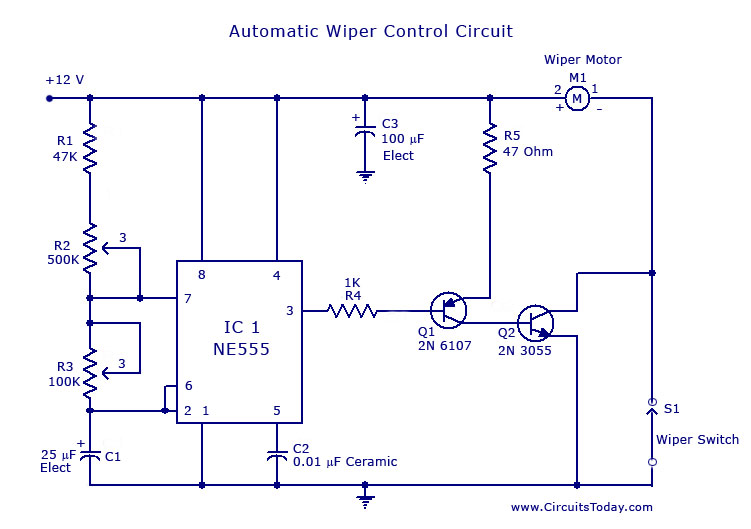
A continuously working wiper is a big problem when it is raining slightly.The wiper control given here makes the wiper to sweep at rates from 1S to 10 S.
The circuit is build around an astable multivibrator using NE 555.Here the output at pin 3 remains high for a time period set by R2 ,and low for a time period set by R3.The low output pulse drives the transistor pair to drive the wiper motor to make one sweeping cycle and waits for next low pulse to arrive for next sweep.The high going pulse at pin 3 determines how many time should wiper should sweep in a given period of time.

Notes

Connect the circuit to 12V line from Vehicle and connect the wiper motor and wiper switch as shown in figure.
For setting the device first find out how much time it is required for the wiper to complete one sweep cycle.Now adjust R3 such that wiper makes correct one sweep cycle.Fix R2 some where on the dash board.And now the system is ready to use.
You can adjust the sweep rate of the wiper using R2 according to the intensity of rain.

Circuit Diagram with Parts List.

Wiper control circuit

Automatic Head Lights Turn Off Circuit


Car Head Lights Turn Off Circuit

Description

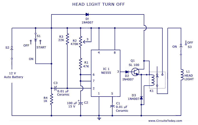
This circuit when setup in a car automatically turns off the head light after a preset time after the ignition switch is turned off.So you can walk out easily from the dark garage in the light of your car.
When the ignition switched on first the voltage from battery is fed to the relay through diode D1.When the ignition switch is turned off it produces a negative going pulse at the pin 2 that triggers the timer. The output of the IC goes high for the time set by R1  .This makes the transistor Q1 to conduct to energize the relay to drive the headlight.After the set time the light goes off.With the value of components used you can make a setting from 10 S to 60 S.

Notes

  • Assemble the circuit on a good quality PCB or common board.
  • Fit the potentiometer on somewhere on the dashboard so that  you can easily set the timing.

Circuit Diagram & Parts List.

head light turn off


Voltmeter circuit using LED


Car Battery Voltmeter Circuit

Description

This is a very useful circuit which when installed on your car gives the voltage of you car battery in a LED dot display form.The circuit is based on four comparators made of quad op amp LM324.The inverting inputs of IC are kept at at reference voltages 5.6V,5.2V,4.8V,4.4V respectively at pins 2,6,9,13 by resistors ,R3,R4,R5,R6.The battery voltage is directly fed to the pin inverting input through the voltage divider arrangement using R1 and R7.When there is variation in the input supply the out put of each op amp goes high accordingly as they are wired as voltage comparators.The corresponding LED glows.

Voltmeter Circuit Diagram and Parts List

Voltmeter Circuit Diagram
Voltmeter Schematic

Notes

  • IC LM 324 consists of4 op amps in one package , so power supply is common and is shown once (pin 4 and 11).
  • To setup , connect  the circuit to battery  ,adjust R6 so that required voltages are available at the inverting pins( refer description to get the required voltages).
  • Fix the LED’s on the dash board and mark the voltages near to it as shown in circuit diagram.The gadget is now ready

Simple battery charger circuit.


Description .
Here is the circuit diagram of a simple and straight forward battery charger that can be used to charge all type of 12V rechargeable batteries including car batteries. The circuit is nothing but a 12V DC power supply with an ammeter for monitoring the charging current.The two diodes forms a centre tapped full wave rectifier .The capacitor filters the rectifier output to produce a clean 12V  out put.
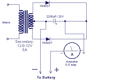
Circuit diagram with Parts list. 
car-battery-charger.gif
Notes. 
  • At initial stages of charging the ammeter will read about 1 to 3 amperes.
  • As the battery is slowly charged the current slowly decreases.
  • When the battery is fully charged the ammeter reading will be zero.
  • Always be careful to connect the charger to the battery in correct polarity. Positive to positive and negative to negative.

Converting CD-ROM drive to audio CD player


Description.
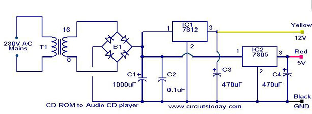
Here is the simplest scheme for converting a CD ROM drive of your computer to a Audio CD player.The minimum requirement for the player is that, it should have a audio output and skip button. Luckily most of the Cd ROM’s are equipped with both of these.

The CD ROM drive needs two voltages ,12V & 5V for its operation.So the main objective is to build a suitable power supply for the CD ROM drive.The IC1 (7812) together with associated components produce a regulated 12V DC.The IC2 (7805) together with associated components produce a regulated 5V DC.These voltages as well as ground can be connected to the corresponding voltage pins of the CD ROM drive using a male type CD ROM drive power connector.The 12V can be connected to the yellow wire of connector, 5V to red wire and GND to black wire as shown in figure1.Now the power supply is ready.
Testing.
Make the circuit as shown in the circuit diagram.Power up the circuit after connecting the power connector to the CD ROM drive. Now the power LED of the drive will glow.Insert the audio CD.Now the music will be available at the audio output socket of the drive.It can be heared using a headphone.The skip button of the drive can be used to play next song.

By connecting the audio output to a power amplifier you can enjoy the music in a greater wattage.
Click Here! to get the amplifier circuits suitable for this project.
Circuit Diagram with Parts list.
cd-rom-audio-cd-converter.JPG
Notes.
  • For car stereo applications you don’t need the transformer,rectifier and the 7812 regulator.12V will be available from battery.You just need to produce a 5V from it using a 7805 based regulator. Connect the corresponding voltages to the connector as shown in figure 1 and connect the connector to drive.Done.
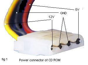
  • The amplifier for the car audio CD player must be one operating from 12V.
  • Do not connect the voltages to CD ROM drive in wrong polarity.Double check the voltages using a multimeter. Wrong polarity could easily damage the drive.
  • cd-rom-drive-power-connector.jpg

Automatic headlight dim switch.


Description.
With this cool circuit integrated to your cars headlight system , you can drive cool headed in high beam.The circuit will take over the duty of low beaming the headlight when vehicles approach against , and high beams the lights when they pass over.
The circuit is based on a photo transistor(Q1) for sensing the approaching vehicles and transistor Q2 (BC177) for switching the relays for controlling the headlight.When the light from the opposite vehicle falls on Q2 , it’s collector current increases and turns ON Q1.The relay will be activated and the head light will be dimmed.When the vehicle pass over the reverse will happen.
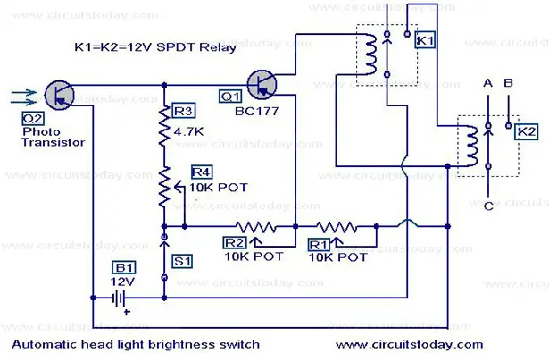
Circuit diagram with Parts list.
automatic-headlight-dim-switch.jpg
Notes.
  • The battery B1 can be the 12V car battery itself.
  • Adjust POT’s R1,R2,R4 to obtain optimum performance.
  • The Q1 can be any general purpose PNP photo transistor.It should be mounted in front of the car so that the light from opposite vehicle easily falls on it.
  • Relay contact A goes to high beam circuit,B to low beam circuit and C is the common point.
  • Carefully understand the wiring of your car before attempting to install the circuit.Wrong connections could easily bring trouble to your cars wiring

Shock alarm circuit


Description.
Here is a simple shock sensitive alarm circuit that has many many applications fro home to automobiles.The main application of this circuit is to use it as an anti theft alarm in automobiles.A peizo electric sensor is used as the shock sensor which has to mounted on the door which you have to protect.
Here the IC1  LM 3558 is wired as an inverting Schmitt Trigger.The POT R1 sets the threshold voltage of the circuit.R1 is used as a feed back resistor.When not activated the out put from the piezo sensor will be low and so do the output of the IC.When the piezo sensor is activated its output voltage goes high and triggers the Schmitt trigger.This results the beeping of the buzzer.The buzzer remains beeping for some time even if the vibration is removed.this is because the increase in the inverting input has little effect when the IC is triggered and the state can’t be easily reversed.
Circuit diagram with Parts list .
shock-alarm-circuit.JPG
Notes. 
  • A 3 v battery can be used as  power supply.
  • Fix the sensor firmly to the surface,where ever you place it.
  • It is always good to place the sensor near to the door knob.
  • Adjust R2 to obtain the required sensitivity.
  • Assemble the circuit on a good quality PCB or common board.
  • Use a IC holder for mounting the IC

FM adaptor circuit for car stereo


Description.
With this compact FM adaptor circuit plugged into the audio out of your cassete player or i Pod out put,you can listen your favorite music on your car stereo.This circuit is very useful if your car stereo doesnot have an auxillary in socket.The circuit is nothing buy  an short range  FM transimitter.
The FM transmitter circuit is based on low power NPN transistor 2N2222.The tank circuit consisting of L1 & C1 producess the necessary oscillations at the collector of Q1.The capacitance C4 , resistance R3 & R4  performs the function of mixing the stereo out put from theaudio player or i-Pod.The emitter resistance R2 provides sufficient stability to the circuit.It also limits the collector current to increse the battery life.
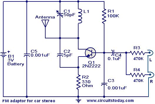
Circuit diagram with Parts list.


fm-adaptor-circuit-for-car-stereo.JPG
Notes.
  • Use a 28SWG , 10 cm insulated copper wire as antenna.
  • For L1.make 8 turns of 20 SWG insulated copper wire on a 5mm dia plastic former.
  • Power the circuit from a 3V battery.
  • Assemble the circuit on a good quality PCB or common board.
  • C1 can be a  50pF trimmer

Lamp flasher circuit


Description.
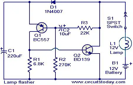
This simple circuit that can be used to flash incandescent lamps up to 10W power rating.The circuit is ideal for making flashing beacons on automobiles and other applications like that.The circuit is nothing but  an astable multi vibrator based on Q1&Q2 ( BC557&BD139).The capacitor C1 is the main timing element which determines the flashing rate of the circuit.The switch S1 can be used as an ON/OFF switch.
Circuit diagram with Parts list.
lamp-flasher-circuit.JPG
Notes. 
  • Power the circuit from a 12 V battery or 12V DC power supply.
  • Assemble the circuit on a goood quality PCB or common board.
  • A 12 v , 10W incandescent lamp can be used as the load.
  • All capacitors must be rated 15V

Head light timer circuit


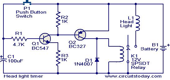
This circuit is a compact timer circuit that will keep the headlights of your car ON for about 1.5 minutes and then turns it OFF.This circuit incorporated to your car will help you to access dark places with out the need to come back and turn OFF the head lights.
When the push button switch P1 is pressed the capacitor C1 is charged to the full battery voltage.As a result the transistor Q1 is turned ON ,which in turns ON Q2 which in turns drives the relay K1 to glow the head lights.The relay K1 will remain activated until the capacitor C1 is fully discharged.The time delay of the circuit depends on values of C1 & R1 and here it is set to be 1.5 minutes.
Circuit diagram with Parts list.

head-light-timer-circuit.JPG
Notes.
  • Assemble the circuit on a good quality PCB or common board.
  • The time delay of the circuit can be varied by varying the values of R1&C2.
  • At most care must be taken while wiring this circuit to your car because a wrong connection could cost you a lot of money.
  • The capacitor C1 must be rated at least 15V

Missing pulse detector circuit using NE555


Description.
An NE555 timer IC connected as shown here can detect a missing pulse or abnormally long period between two consecutive pulses in a train of pulses,Such circuits can be used to detect the intermittent firing of the spark plug of an automobile or to monitor the heart beat of a sick patient.
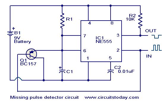
The signal from the pick up transducer is shaped to form a negative going pulse and is applied to pin 2 of the IC which is connected as a mono stable.As long as the spacing between the pulse is less than the timing interval,the timing cycle is continuously reset by the input pulses and the capacitor is discharged via T1.A decrease in pulse frequency or a missing pulse permits completion of time interval which causes a change in the output level.


Circuit diagram with Parts list.
missing-pulse-detector-circuit.JPG

Notes.
  • Assemble the circuit on a good quality PCB or common board.
  • The circuit can be powered  from a 9V battery or 9V DC power supply.
  • The IC1 NE555 could be mounted on a holder

Page Rank

google pagerank

Write For Us

Submit a Guest Post

Find us on Facebook

Categories

555 Timer IC 7 segment Display 8051 Project AC Circuits Adafruit Alarms Amplifier Circuits Analog Circuits android Arduino arm processor Assembly Languange Atmel Atom Size Audio Circuits augmented reality Automotive Circuits avr Battery Circuits Bicycle Gurad bluetooth Cable TV Circuits Cambridge University Camera Technology Circuit Boards Clipping And Clamping Circuits Clocking And Timer Circuits Computing contact lens Contact Us Form Contests Controller Circuit Conversion Circuits Counter Circuits Digital Electronics diy circuits Downloads EFY EFYTimes Electronic Books Electronic Components Electronic Locks And Keys Engineering Fan Circuits Filter Circuits Fire Alarm free Frequency Fun And Game Circuits future Google Hack n Mod Ham Radio Circuits heart rate monitoring High Voltage Circuits Home Circuits IC Guide ieee Industrial Circuits Infrared Instructables Inventions ipad lcd Led Circuits Light Related Lighting Circuits Medical Circuits Meter Clocks Microcontrollers Microprocessors Mini Projects modules Movie maker NatGeo Navigation Notice Optical Fiber PC Circuits PCB Boards Physics pnp transistor Power Supplies Printing Projects Programmer Project Ideas Projectors Protection circuits Proximity Detectors Radar Radio Circuits Radio Transmitters Raspberry Raspberry Pie Remote Circuits Retis Lab RFID Robot Cars Robotics Science Science Alert Security And Safety Sensor Circuits Servo Motors Smallest Smartwatches sms Software solar cell sound application Spectram Switch Technology News Telephone Related Television Related Test And Measurement Circuits Thermal Projects Tone generator circuits Touch Screen Tutorials Wearables Wi-Fi Wireless
Like us on Facebook
Follow us on Twitter
Recommend us on Google Plus
Subscribe me on RSS