Search This Blog

Powered by Blogger.

Translate

[TC] Arduino Video Game for the Neighbourhood update 2014


My house/office has a store window and I try to make use of it as much as possible. I had some projections etc. in there before, but now I wanted to make something interactive. We have a lot of loitering youth and many people passing by. To appeal to a wide audience, I thought it would be nice to make an old fashion arcade box like thing.
It’s now on the street for one day and people really seem to like it. Age or background doesn’t make a difference.
To make it a little bit more challenging,  I thought it would be fun to try to run the hole thing on an Arduino without an external computer. Just to see how much power it actually has. And while I was at it, I decided to try to make everything myself. So I also made my own led screen, with his own “display driver” and display list, a 8-bit sound library, and of course the game itself.
The only thing I didn’t make was the background music for the game, that was composed by the lovely Annegreet Sledsens: Thanks sweety!  You can hear it in the video.
The led screen is very bright which made it very hard to film and photograph with my cheap camera. Even after some photoshopping, I couldn’t  make it look as good as in real life. So if you’re in the neighbourhood (Antwerp Belgium, Provinciestraat 60, behind the Zoo), feel free to come check it out and play a game with the locals!
Here the video and some more pics:


The Game


I needed something that would appeal to a large audience (the people in my street) and something was fun to play .
So I took the good old gaming cliché, where the world gets invaded by aliens and you have to fight your way to the end boss, save the world and the human race . With my minimal resolution of 16*90 pixels, I didn’t have much other choice than making it pixel-art style.

The game has 3 modes, a single-player and a multiplayer brawling/fighting the aliens mode, and an extra fighting mode where the 2 players can battle with each other.
Every mode has just one level, but since it is just a casual “play on your way to work” kind of game, I thought it would be more then ok.
some screen-shots:

The game-mode selection:

Two players fighting the the final boss:

The girl kicking the boys ass in fighting mode:

Game over!


Development


To make the development easy and fast, I cross developed the game as a Cinder c++ app  and an Arduino app, that way i didn’t had to upload the whole thing on an Arduino every time I wanted to test something.

I didn’t use any external memory, so I had to store everything on the Arduino.  I made a small app that generates c++ classes from bitmaps with some gamma correction for the led screen. I used indexed colours to save some of that precious SRAM. For driving the leds, I modified the Adafruit neopixel lib, to support alpha-blending and make it a little bit faster for my specific case.
I don’t really have much experience with generating sound and music. So the 8-bit sound was quite challenging. I’m happy with the result, but my oscilloscope broke during development of a more advanced sound lib, so its quite simple for now. But I really enjoyed  myself working on the sound aspect. I have a feeling that my next project is going to be something sound/music related ;)
I’m not going to elaborate too much on the rest of the code. But you’re free to check the source code yourself  (warning: its messy).
The full source code and game assets on Github (Code-> MIT, Assets-> CC attribution)

The Hardware


Like I said, I made my own led display.

I used strips of  WS2812 LEDs, those are individually-addressable RGB LEDs. The lay in a 16*90 grid (=1440 leds)
I added a laser cut raster over the leds to make the pixels square and put a layer of plexi to diffuse the light some more.

Beneath the leds is the main Arduino Due and the power source. This is the Arduino that drives the display and runs the game. Those leds suck a lot of power , so I had to add a 60A 5V power supply.

The screen/main arduino is connected with the arcade box through a simple tx-rx serial line, which was fast enough to send the button commands.
the arcade box is just some painted MDF with a steel frame inside, and a steel plate on-top (it has to be a little bit solid if i leave it outside ;) )
The Arduino in the arcade box generates the sound and music and handles the raw button/joystick input.


If your interested,  the full “schematic” of the project:
Its pretty straight forward.: Pulldowns for the buttons and joystick, the led connections and a pot for the screen brightness and a tx-rx line between the two Arduinos.
on top of that there is a DC coupling for the speaker which is connected to the Arduino DAC . But I still have to put some kind of amplifier between the arduino and the speakers. The sound is hard to hear because of the street noise.


[TC] Secure Digital Access System using iButton


Access control forms a vital link in a security chain. Here we describe a secure digital access system using iButton that allows only authorised persons to access a restricted area.


The iButton is used here as a key to the access control system. Its unique identification (ID) number is used for authorisation. On detection of an authorised iButton, the system allows access. Thereafter, an automated lock key locks the system again. The system is permanently halted after five repeated false attempts. A service control unit built around an AVR microcontroller is interfaced to the iButton with 1-wire protocol for authentication of user validation of data.


iButton DS1990A
Here we have used the iButton DS1990A from Dallas Semiconductor (MAXIM). Its block diagram is shown in Fig.1.


Fig.1: Block diagram of iButton
An iButton is a chip housed in a stainless-steel enclosure (refer Fig.2). The electrical interface is reduced to the absolute minimum, i.e., a single data line plus a ground reference. The energy needed for operation is taken from the data line. The DS1990A serial number iButton is a rugged data carrier that acts as an electronic registration number for automatic identification. It contains a unique ROM code that is 64-bit long as shown in Fig.3. The first eight bits are a 1-wire family code. The next 48 bits are a unique serial number. The last eight bits are a cyclic redundancy check (CRC) of the first 56 bits.


Fig.2: A typical iButton chip

Data is transferred serially via the 1-wire protocol, which requires only a single data lead and a
ground return. The iButton DS1990A provides the additional 1-wire protocol capability that allows the search ROM command to be interpreted by the DS1990A.


Fig.3: 64-bit lasered Rom


Circuit description

Fig.4 shows the circuit of the secure digital access system using iButton. The circuit is built around an ATmega16 microcontroller.


Fig.4: Circuit of the secure digital access system using iButton


The ATmega16 is an 8-bit microcontroller based on the AVR enhanced RISC architecture that executes powerful instructions in a single clock cycle. It has 16kB in-system programmable flash program memory with read while- write capabilities, 512 bytes of EEPROM, 1kB SRAM, 32 general purpose input/output (I/O) lines, 32 general-purpose working registers,three flexible timers/counters with compare modes, internal and external interrupts, a serial programmable. USART, a byte-oriented two-wire serial interface, a programmable watchdog timer with internal oscillator, an SPI serial port and six software-selectable power-saving modes.

Piezobuzzer PZ1 is used as an audible indicator for true, fake, random touches and system halt. It is controlled from port pin PD6 of the microcontroller with the help of transistor T1. The iButton socket is connected to port pin PD2. Pull-up resistor R1 is used as required from the 1-wire protocol. Port pin PD4 controls the relay operation through optocoupler PC817 (IC2). The door locking mechanism, say, for a slide door, is connected to the contacts of relay RL1, which closes after some time automatically.

Whenever someone attempts to gain access by touching the iButton (IC5) using his own iButton, the firmware inside the AVR reads its unique ID and matches with the ID in the firmware. If the ID matches, port pin PD4 goes high, the internal LED of the optocoupler (IC2) glows and relay RL1 energises for the predefined time. Simultaneously, the buzzer sounds to indicate grant of access.

Thereafter, relay RL1 de-energises. The buzzer gets the PWM signal to produce sound from port pin PD6 of the microcontroller. The 1-wire communication is done through interrupt port pin PD2 (INT0), so the AVR does not have to poll the pin but respond when any change in signal is detected on the interrupt pin. Switch S1 is used for manual reset.

Port pin PD1 of the microcontroller is used to interface with the hyper terminal of the PC through RS-N 232 interface MAX232 IC (IC3) for iButton verification and checking. The microcontroller  provides a transmit channel for serial data transfer. Transmit data pin (TXD) is specified at port pin PD1. The microcontroller is connected to T1 IN (pin 11) of MAX232. T1 OUT (pin 14) of IC3 is connected to pin 2 of the Comport connector. The signals provided on these pins are TTL-level and must be boosted and inverted through a MAX232 converter to comply with the RS-232 standard.


The MAX232 has two internal charge pumps that convert +5V into ±10V (unloaded) for RS-232 driver operation. The first converter uses capacitor C6 to double the +5V input to +10VM on capacitor C8 at pin 2. The second converter uses capacitor C5 to invert +10V to -10V on capacitor C4 at pin 6.

The power supply for this circuit is derived from 230V, 50Hz AC mains. Transformer X1 steps down 230V, 50Hz AC mains to deliver a secondary output of 9V, 300 mA. The transformer output is rectified by a full-wave rectifier comprising diodes D1 through D4, filtered by capacitor C1 and regulated by IC 7806 (IC4). Capacitor C2 bypasses the ripples present in the regulated supply. LED1 acts as the power indicator and R5 limits the current through LED1.
Construction and testing
An actual-size, single-side PCB for the secure digital access system is shown in Fig. 5(View as PDF) and its component layout in Fig. 6(View as PDF). Assemble the circuit on a PCB as it minimises time and assembly  errors. Carefully assemble the components and double-check for any overlooked error. Connect the assembled circuit to the COM port of the computer. The iButton access code and message is transferred is to the PC through the COM port using the Hyper Terminal program.


Software
The software for this project is given at the end of this article. It is written in ‘Basic’ language and compiled using Bascom-AVR compiler. The source program is well commented and easy to understand.

Burn the finally obtained Intel hex code file into the AVR’s flash memory using a suitable programmer. The microcontroller uses an 8MHz internally generated clock. To activate, program fuse bytes as follows:


Fuse low byte = D4
Fuse high byte = 99

The source program is developed quickly with the help of the BASCOMAVR library function. The 1wrest, 1wread and 1wwrite functions are used for checking the presence of 1-wire device, reading of the unique ID of iButton and writing to the 1-wire device, respectively. Sound function is used for generating the beep sound from the buzzer. The iButton is connected to hardware interrupt pin INT0 so that any change on the pin can be detected and further processing for 1-wire done.
The program execution starts by initialising the input/output ports, the interrupt pin and its level of detection. Global interrupts are enabled and the interrupt service routine is ready to be executed when any interrupt is received. As soon as the normal program execution is interrupted, an interrupt is issued and the control of execution enters the interrupt service routine, where iButton is given reset command first and then the ROM command to fetch the unique ID of the iButton. This fetched ID is compared with the unique ID programmed in the firmware. If there is a mismatch between the two IDs, a fake parameter counter is incremented and the relay connected to port PD4 de-energises. If the two IDs match, the relay connected to port PD4 energises and simultaneously the buzzer connected to port PD6 sounds. If the unique ID is wrong sequentially five times, the system enters the major warning state where the buzzer sounds continuously and it can only be stopped by resetting the system


Author:Chirutkar Harshadkumar Govindrao And Dr. H.N. PandyaSource:http://www.electronicsforu.com/
 

Android Applications For Electronics And Electrical Engineers

The world around us is changing at a much faster pace than any one can anticipate. The world of “computing” has already seen great shifts from Desktops to Notebooks to Smartphones and Tablets. The coming decade will be more focused on mobile computing and cloud computing. Here in this article, I am listing some of the best and really useful applications released in Android market (aka Google Play), that comes handy for any one who is working in Electrical and Electronics industries/professions. 
Best and Free Android Applications for Electronics and Electrical Engineers
ElectroDroid – is the most popular and useful application in Android market for an electronics engineer. This app is a collection of many simple and useful tools like Resistor color code calculator, Filter value calculator, Inductor color code calculator, SMD resistor code calculator,  LED resistor calculator etc. The App also has a great collection of pin out diagrams of USB port, Parallel port, Ethernet port, VGA connector, Firewire connector etc and other resources and references which lists PIC micro controller database, ISP specs of AVR and PIC, Circuit schematic symbol reference, ASCII table references, Battery references etc.  This application has been downloaded by more than 10,000,00 smart phone devices and has been rated by more than 30,000 users. If you are looking for a much better version of the app without ads, you can buy it from the Google Play store (Electrodroid Pro) for less than 3 USD
Best and Free Android Applications for Electronics and Electrical Engineers
EveryCircuit - is a simple and beautiful application for android which helps you to build and simulate circuit ideas. It has a really good & simple user interface which begins with a workspace where you can start building your circuits. You can add your components like resistors, capacitors, inductors, power sources, signal sources etc and wire them together to complete the circuit. You can alter the values of each and every component and then finally Run/Simulate them. You will see the current flow, input and output waveforms graphically represented etc when you run the circuit you have built. You can alter the component values in real time and see the changes in output instantly. Additionally the app developers have provided a set of built in circuit applications like inverting amplifier, rectifier circuits, voltage regulator etc which the user can simulate instantly to learn the working of these circuits. The attractive feature is the graphical representation (animation) of the electron flow, input and output signals which helps the user to understand the circuit functioning within no time.  Their free version doesn’t have a large work space area, which limits the number of components you can play with. They also have limited their component library in their free application. I think they have deliberately done this to promote their paid application –EveryCircuit Premium – which they sell for around 10 USD. They have sold more than 10,000 apps in Play store, which shows people are quiet interested in their appI suggest you try their Free app first and if you like it, go ahead and buy the premium version.
Best and Free Android Applications for Electronics and Electrical Engineers
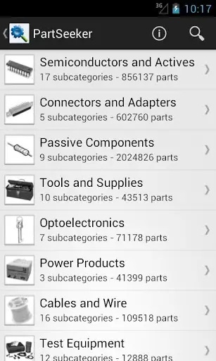
PartSeeker – is an app for searching electronic parts and components. Unfortunately this app is a paid one and the good side is that you can buy it for less than 2 USD. This app is made and released by the same company (IERO) which made ElectroDroid (see above) app. IERO has made this app by using the extensive component library of Octopart (the electronic component search engine). This app comes handy while you are away travelling and is keen to search for a component using your mobile device (may be smart phone or a tab!). 
Best and Free Android Applications for Electronics and Electrical Engineers
PIC Microdatabase - another free app from IERO, which integrates well with ElectroDroid app. This app is nothing more than a database of PIC micro controllers manufactured by Microchip. This app lists all PIC and dsPIC family of controllers in an easy to use user interface. Features and specifications of all controllers along with pinout diagrams of select ones are available. The most attractive feature is a search functionality in which you can search for a controller with particular features you would like to have.As an example you can search for controller from PIC that belongs to a particular PIC family like PIC 10, with specific EPROM values, specific RAM, USB 2.0 or higher, specific internal oscillator values  etc. The app will output all PIC controllers that matches your search criterias. So far more than 10,0000 users have downloaded this application.
Best and Free Android Applications for Electronics and Electrical Engineers
DroidTesla – is another free app for simulating electronic circuits. This SPICE simulation tool is quiet similar to the app “EveryCircuit” mentioned above in its functionality - means you can build and simulate a circuit. But they both (EveryCircuit and DroidTesla) differ in user interface and features provided. I found the free version of “EveryCircuit” much more appealing than DroidTesla. EveryCircuit has certain predefined circuits like halfwave rectifier, inverting amplifier etc which you can simply load to workspace and simulate in realtime. DroidTesla has given a list of examples in their free app version but none of them loads properly to workspace. The reason is most of the example circuits contain a particular component which may be available only on DroidTesla’s commercial version. User interface of  EveryCircuit is much better than that of DroidTesla. DroidTesla’s commercial version might be much better than EveryCircuits premium version, as DroidTesla has large set of component library to choose from. DroidTesla will definitely outshine EveryCircuit – if the number of component libraries available is taken into account. Both of the apps commercial versions are priced competitively. If “user interface” is your primary preference, I will recommend EveryCircuit premium. On the other hand, if number of component library is your first preference, I shall recommend DroidTesla commercial version
ElectronicsToolKit – is another free app which is a collection of simple tools like resistor color code calculator, series and parallel calculator etc. Almost all those tools are available in ElectroDroid app too, except for a Power Triangle calculator. I have listed this app here as it is free (and I have spent some time to download and test this app in my Galaxy) and you guys can try out, if you have time.More than 10,000 users have tried this application.
Best and Free Android Applications for Electronics and Electrical Engineers
AllDataSheet App – This app is free version of the Datasheet website Alldatasheet.com. This app is nothing more than a book mark to alldatasheet website’s mobile version. I dont recommend you to download this app as your purpose will be served by visiting Alldatasheet.com from your mobile browser (which will get automatically redirected to mobile version) 
EquivalentResistanceSolver – is another free app which helps you to calculate the equivalent resistance of a circuit. This app may not be that useful for a professional as the “user interface” is average. It takes lots of time to build a “Series-Parallel” combination. Might be handy for students who are learning about the concepts for the first time. 
RF Pad Calculator – is a free app that helps to calculate the resistor values required to build an RF attenuator. 
AmpliCalc - is a simple and free app to calculate inverting and non inverting operational amplifier values.
FilterCalc – is another free app from the same developer of Amplicalc, which helps to realize filter design by finding the appropriate values. 
ControlCalc – is yet another free app from the same developer of Amplicalc, which helps in simulating closed and open systems, calculate transfer functions, state response & you can save the output as PNG. 
M32 Assembly – is another interesting application which helps you to learn assembly language by yourself. This app infact is a simulator for the M32 processor.
Electronica – is another app which is open source (the source code of this app is available for free download). This app is also a collection of simple and easy to use tools that comes handy for an every day electronics enthusiast/professional or even a student.   
There are a handful of other free android applications like Ohms Law calculator, 555 Timer Calculator which I have not mentioned here. The reason is simple, most of the “electronics tools apps like ElectroDroid, Electronica, ElectronicsToolsKit etc has Ohms Law calculation, Resistor Colourcode calculation and 555 Timer calculator embedded in them!

Source:Circuitstoday.com

Your Own 89S Series Programmer

Circuit Diagram :

 
PCB  :


USB :


PC Software :
 

Download:
 

Page Rank

google pagerank

Write For Us

Submit a Guest Post

Find us on Facebook

Categories

555 Timer IC 7 segment Display 8051 Project AC Circuits Adafruit Alarms Amplifier Circuits Analog Circuits android Arduino arm processor Assembly Languange Atmel Atom Size Audio Circuits augmented reality Automotive Circuits avr Battery Circuits Bicycle Gurad bluetooth Cable TV Circuits Cambridge University Camera Technology Circuit Boards Clipping And Clamping Circuits Clocking And Timer Circuits Computing contact lens Contact Us Form Contests Controller Circuit Conversion Circuits Counter Circuits Digital Electronics diy circuits Downloads EFY EFYTimes Electronic Books Electronic Components Electronic Locks And Keys Engineering Fan Circuits Filter Circuits Fire Alarm free Frequency Fun And Game Circuits future Google Hack n Mod Ham Radio Circuits heart rate monitoring High Voltage Circuits Home Circuits IC Guide ieee Industrial Circuits Infrared Instructables Inventions ipad lcd Led Circuits Light Related Lighting Circuits Medical Circuits Meter Clocks Microcontrollers Microprocessors Mini Projects modules Movie maker NatGeo Navigation Notice Optical Fiber PC Circuits PCB Boards Physics pnp transistor Power Supplies Printing Projects Programmer Project Ideas Projectors Protection circuits Proximity Detectors Radar Radio Circuits Radio Transmitters Raspberry Raspberry Pie Remote Circuits Retis Lab RFID Robot Cars Robotics Science Science Alert Security And Safety Sensor Circuits Servo Motors Smallest Smartwatches sms Software solar cell sound application Spectram Switch Technology News Telephone Related Television Related Test And Measurement Circuits Thermal Projects Tone generator circuits Touch Screen Tutorials Wearables Wi-Fi Wireless
Like us on Facebook
Follow us on Twitter
Recommend us on Google Plus
Subscribe me on RSS