Search This Blog

Powered by Blogger.

Translate

Tutorial: Making Solar Cell Using 2N3055 Transistor


This video unveils the fact that a silicon diode is quite similar to a solar cell. To prove this, it takes apart a 2N3055 power transistor to produce 1.6 milliwatts. Watch the video for a great tutorial on creating a transistor solar cell.

It's easy to cut open a power transistor like the 2N3055 to expose the NPN silicon material inside to make a solar cell. When exposed to sunlight, or household lights, it conducts electricity. The N-type and P-type materials work like a solar cell. The best way is from the Base to the Collector though from both the Base and Emitter combined and then to the Collector also works well. The voltage and current aren't much but with just a few of them in series you can power a small 1.5 volt calculator.


Source: http://electronicsforu.com/newelectronics/video/detailvideo.asp?id=2077

Water level alarm circuit


Description.
Here is a simple water level alarm circuit that will produce an audible alarm when the water level reaches  a preset level.The circuit can be powered of a  3V battery and is very handy to use.
The circuit is based on an astable multivibrator wired around IC1 (NE 555).The operating frequency of the astable multivibrator here will depend on capacitor C1, resistances R1,R2 and the resistance across the probes A&B.When there is no water up to the probes,they will be open and so the multivibrator will not produce oscillations and the buzzer will not beep.When there is water up to the level of probes,some current will pass through the water,the circuit will be closed to some extend,and the IC will start producing oscillations in a frequency  proportional to the value of C1,R1,R2 and the resistance of water across the probes.The buzzer will beep to indicate the presence of water up to the level of the sensing probes.
Circuit diagram with Parts list.
water-level-alarm-circuit.JPG
Notes.
  • The circuit can be powered of a 3V battery.
  • Assemble the circuit on a good quality PCB or common board.
  • The probes can be made of two insulated copper Aluminiun wires.
  • Place the probes at the position where you have to sense the level

Door bell circuit using NE555


Description.
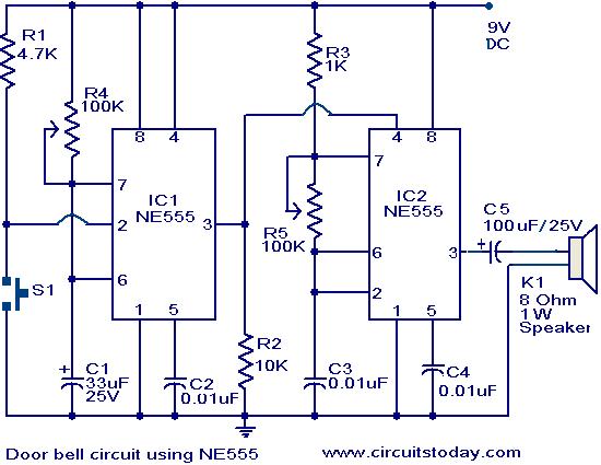
The main part of this doorbell circuit are two NE555 timer ICs.When some one presses switch S1 momentarily ,the loud speaker sounds a bell tone as long as the time period of the monostable multivibrator built around IC1.
When the switch S1 pressed, IC1 is triggered at its pin 2 and output pin 3 goes high for a time period previously set by the values of POT R4 and POT R5.When the output ofIC1 goes high it resets IC2 and it starts to oscillate to make a bell sound through the speaker.The IC2 is configured as an astable multivibrator whose oscillation frequency can be varied with the help of POT R5.By adjusting the values of R4 & R5, modifications on the tone are possible.
Circuit diagram with Parts list.

door-bell-circuit-using-ne555.JPG
Notes.
  • The circuit has to assembled on a good quality PCB or common board.
  • The IC1 & IC2 has to be mounted on IC holders.
  • Power the circuit from a 9V battery or 9V DC power supply.
  • Switch S1 is push button switch

Remote controlled appliance switch circuit


Description.
Here is a versatile remote controlled appliance switch that can ON or OFF any appliance connected to it using a TV remote.
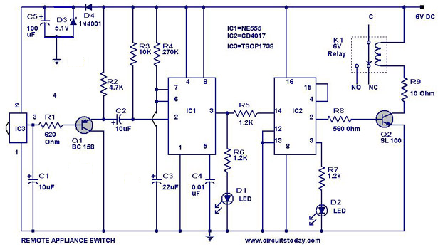
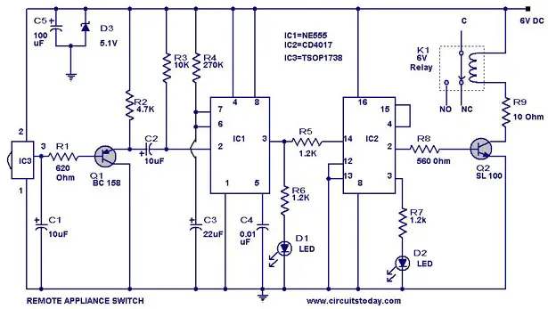
 IR remote sensor IC TSOP 1738 is used for recieving the signal. Normally when no signal is falling on IC3 the output of it will be high.This makes Q1 OFF.When a signal of 38 KHz from the TV remote falls on the IC3 its output goes low.This makes Q1 conduct and a negative pulse is obtained at pin 2 of IC 1  NE 555.Due to this IC1 wired as a monostable multivibrator produces a 4 Sec  long high signal at its out put.This high out put is the clock for IC 2 which is wired as a Flipflop and of , its two outputs pin 3 goes low and pin 2 goes high.The high output at pin 2 is amplified to drive the relay .For the next signal  the outputs of IC2 toggles state. Result, we get a relay toggling on each press on the remote.Any appliance connected to this circuit can be switched ON or OFF.
Circuit Diagram with Parts List .

Notes.
  • Before wiring the circuit make sure that the carrier frequency  of the TV remote you have is 38 KHz.For that wire the sensor part only ,point your remote to the TSOP1738 and press any switch.If  out put of TSOP1738  goes  low them ok, your remote is of 38Khz type.Nothing to worry almost all TV remote are of this type.
  • You can use any switch because for any switch the code only changes,the carrier frequency remains same.We need this carrier frequency only.
  • Assemble the circuit on a good quality PCB or common board.
  • The appliance can be connected through NO or NC  and contacts of the relay


Transistor intercom circuit.


Description.
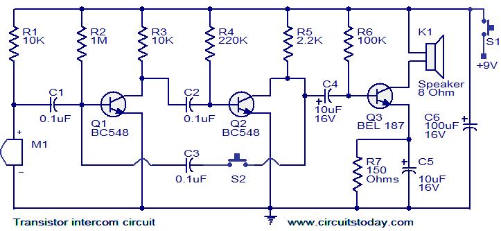
Here is a simple but effective intercom circuit that is based fully on transistors.The circuit is based on a three stage RC coupled amplifier. When the pushbutton S2 is pressed, the amplifier circuit wired around T1 & T2 becomes an astable multivibrator and starts producing the ringing signals. These ringing signals will be amplified by the transistor T3 to drive the speaker. When the push button S2 is released the circuit will behave as an ordinary amplifier and you can talk to the other side through it.
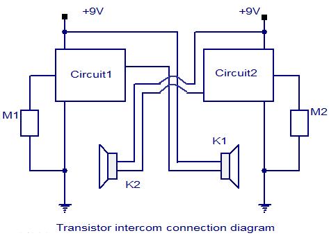
To construct a two way intercom, make two identical copies of the circuit given below and connect it according to the given connection diagram. The stand by current consumption of this circuit is around 20mA.

Circuit diagram with Parts list.
transistor-intercom-circuit.jpg

Connection diagram. 
 transistor-intercom-connection-diagram.jpg

Notes.
  • Assemble the circuit on a good quality PCB.
  • Use 9V PP3 battery for powering the circuit.
  • The Mic M1 can be condenser micro phone.
  •  Use push to ON type push button switch for S2.
  • Use a slide switch for switch S1.S1 can be used to power the circuit

Night security light


Description.
Here is a simple circuit switches on a light around 2 hours after midnight, the time at which most of the robberies taking place.
This simple circuit is build around a CMOS IC 4060 to obtain the required timing. During day time the LDR has low resistance and keeps the pin 12 of the IC1 high, preventing the IC1 from oscillating. When it is dark the LDR resistance becomes high and the pin 12 of IC1 becomes low and the IC starts oscillating, which indicated by the flashing of LED D3.The values of the timing components R1, R2, C4 are so selected that the out put pin3 of IC1 goes high after 8 hours. That means the high output drives the triac to switch on the lamp around 2’O clock. At morning, the LDR resistance drops and the pin 12 of IC1 goes high and stops the oscillation, making the lamp OFF. The switch S1 can be used to manually ON the lamp. The capacitor C2 prevents false triggering.
Circuit diagram with Parts list.
night-security-light
Notes.
  • Assemble the circuit on a good quality PCB or common board.
  • The LDR can be general purpose LDR.
  • The light sensitivity can be adjusted using the preset R6.
  • The IC1 must be mounted on an IC holder

Plant moisture level monitor


Description.
Here is a simple circuit that will give a visual indication when the soil water level inside your flower pot goes low below a certain limit.
The U1C and associated components are wired as an oscillator producing a 2KHz square wave. This square wave is given to one gate input of U1D via a variable potential divider former by R1 and R2.When the resistance across the probes A and B are low that is when soil moisture level is high, the C2 will divert the square wave to ground. The output of U1D will be high. The U1 A inverts this high state to low and so the IC U1B is blocked from producing oscillations. The LED will remain OFF. When there is no moisture across the probes, the C2 cannot bypass the 2KHz signal to the ground and it appears at the gate input of U1D.The output of U1D goes low, and it is inverted to high by U1A.The oscillator wired around U1B is activated and it starts oscillating. These oscillations are amplified by Q1 to drive the LED and LED starts pulsating as an indication of low moisture. Since square wave is used there won’t be any oxidation on the probes. The resistor R7 limits the current through LED and ensures a longer battery life.
Circuit diagram with Parts list.
plant-watering-monitor-circuit
Notes.
  • Power the circuit from a 3V battery.
  • Two metal wires 10 cm long and 5cm apart driven into the soil will do the job for probes.
  • The probes are to be connected at the terminals A and B shown in circuit.
  • Capacitors C1 and C2 must be polyester type.
  • The IC U1 is a quad two input Schmitt NAND IC 4093.
  • The sensitivity can be adjusted by varying the preset R2.
  • Mount the IC on a holder.


Battery operated heater


Description.
Here is a simple heater circuit that can be operated from a 12V battery. The first part of the circuit is an astable multivibrator build around the two transistors Q1 and Q2 .The ON time of transistor Q2 is set to 0.5 S. The ON time of transistor Q1 can be varied by using the POT R2.The output pulses at the collector of Q2 is used to drive the Darlington power transistor Q3(TIP122).The transistor Q3 drives the heating elements L1 to L3.The net heat produced can be varied by  selecting the desired combination of heating elements at the output circuit sing switches S1 and S2.The net heat can be also varied by varying the duty cycle of the triggering pulse using POT R2.
Circuit diagram with Parts list.
battery-operated-heater-circuit
Notes.
  • The circuit can be assembled on a general purpose PCB.
  • The transistor Q3 must be fitted with a heat sink.
  • The elements L1 to L3 can be 10W heating coils.
  • The switches S1 and S2 must be able to withstand at least 5A.
  • The circuit can be powered from a 12V battery.
  • The LED D1 gives a visual indication of the duty cycle of the circuit

Electronic mosquito repeller


Description.
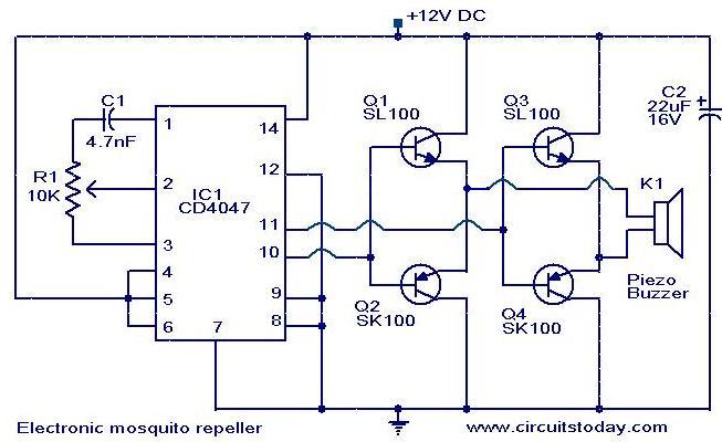
Here is the circuit diagram of an ultrasonic mosquito repeller.The circuit is based on the theory that insects like mosquito can be repelled by using sound frequencies in the ultrasonic (above 20KHz) range.The circuit is nothing but a PLL IC CMOS 4047 wired as an oscillator working at 22KHz.A complementary symmetry amplifier consisting of four transistor is used to amplify the sound.The piezo buzzer converts the output of amplifier to ultrasonic sound that can be heard by the insects.
Circuit diagram with Parts list.
electronic-mosquito-repeller9
Notes.
  • Assemble the circuit on a general purpose PCB.
  • The circuit can be powered from 12V DC.
  • The buzzer can be any general purpose piezo buzzer.
  • The IC1 must be mounted on a holder

LED torch using MAX660


Description.
This is a simple LED torch circuit based on IC MAX660 from MAXIM semiconductors. The MAX 660 is a CMOS type monolithic type voltage converter IC. The IC can easily drive three extra bright white LEDs.The LEDs are connected in parallel to the output pin 8 of the IC. The circuit has good battery life. The switch S1 can be a push to ON switch.
Circuit diagram with Parts list.
led-torch-using-max660
Notes.
  • Assemble the circuit on a general purpose PCB.
  • The IC must be mounted on a holder.
  • The circuit can be powered from two torch cells connected in series.
  • The capacitors C1 and C2 must be Tantalum type.
  • The diodes D1 to D3 must be of 1N4148

How to make a Rheostat


Components

  1. The components needed for the connection are
  2. Flashlight bulb and socket [1]
  3. Dry cell lantern battery/D-cell battery [2]
  4. Wire [About 15 to 17 inches and another one 2 inches]
  5. Spring [1]
  6. Wire Clippers [A pair]
  7. A typical spring can be obtained from a widow roll up. You can even get to buy one at a cheap rate.

Procedure

  • Connect the two Dry cell lantern/D-cell batteries tail-to-tail, so that the positive polarity of one battery is connected to the negative polarity of the other.
  • Using a wire cutter, cut the wire in equal lengths. One wire should be at least 8 centimetres long.
  • Connect the wires onto the open ends of both the batteries.
  • The end of one wire must be connected to the bulb socket with the bulb in it.
  • Connect the second wire to one end of the long spring.
  • Connect the free end of one wire to one terminal of the light socket.
  • Connect the other free wire to one end of the spring.
  • Take the two inch wire and connect it to the second terminal of bulb socket.
  • Connect the other end of the two inch wire onto the other end of the spring.
How to make a RheostatHow to make a Rheostat

How to make a Rheostat
What happens?

As soon as the circuit is in closed loop, the bulb begins to glow. Although the glow intensity is less, when you move the wire through the spring onto the other end where the wire is connected, the bulb starts to glow more brightly. When both the wires are nearby the glow will be in its maximum.
The spring is mainly made of steel wire. Steel wires are not very good conductors of electricity. Thus the resistance of the circuit also increases. If the spring length is long enough you will get to see different stages of the glow. Thus you will get to see the working of a rheostat


Water level Controller


Water level controller circuit.

Description.
A simple but very reliable and effective water level controller circuit diagram is shown here. The circuit uses 6 transistors, 1 NE555 timer IC, a relay and few passive components. The circuit is completely automatic which starts the pump motor when the water level in the over head tank goes below a preset level and switchess OFF the pump when the water level in the over head tank goes above the full level.
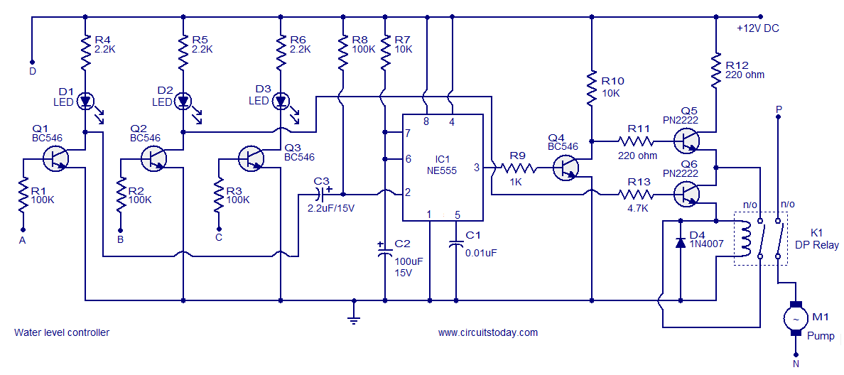
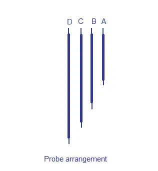
Probe D is positioned at the bottom level of the tank while probes A, B and C are placed at full, half and medium levels of the tank respectively. The level sensing part of the circuit is built around transistors Q1, Q2 and Q3. When water level is below the quarter level probes A, B and C are open and the transistor Q1, Q2 and Q3 remains OFF. When the water level rises and touches the probes the corresponding transistors gets biased and switches ON. Resistors R1, R2, R3 limit the bases current of corresponding transistors while resistors R4, R5, R6 limit their collector current. LEDs D1, D2 and D3 provide a visible indication of the current water level.
When the water level goes below medium, transistor Q2 gets switches OFF and its collector goes positive. Collector of Q2 is connected to the base of transistor Q6 and as result transistor Q6 gets switched ON. Transistor Q5 will be also ON because its base in connected to the collector of Q4 which is presently OFF. As a result when the water level goes below medium relay K1 gets energised and the pump is driven. The relay is wired in the latching mode so that even if the water level goes above medium level the pump remains ON so that the tank gets completely filled. For wiring the relay in latching mode one set  of N/O contacts is used. When relay is activated these contacs close which forms a short across collector and emitter of Q6. This makes the state of Q6 irrelevant to the opertion of the relay and the relay remains ON as long as the transistor Q5 is ON. The only way to make the relay OFF is by switching OFF Q5 and it is done automatically when the water level reaches the full level.
Collector of transistor Q1 is connected to the trigger pin (pin2) of IC1. When the water level reaches full level the transistor Q1 gets switched ON. As a result its collector goes to ground level which triggers the IC1 which is wired as a monostable. The output of IC1 goes high for about 1S. This makes the transistor Q4 ON for the same time and transistor Q5 whose base is connected to the collector of Q4 is switched OFF cutting the supply to the relay. This makes the motor OFF and it remains OFF until the water level again goes below the medium level.
Resistor R8 is a pull up resistor for the trigger pin of the NE555. Capacitor C3 couples the collector of Q1 to the trigger pin of NE55 and facilitates edge triggering whenever the transistor Q1 goes ON. A monostable circuit can be made edge triggered by connecting the trigger signal to the trigger input pin through a capacitor. The capacitor blocks DC and passes sudden changes. The circuit used here is termed as negative edge triggered because the monostable is triggered when ever the trigger input signal falls. R10 and R12 limits the collector current of Q4 and Q5 respectively while R9 and R11 limits their base current. R13 limits the base current of Q6 while D4 is a freewheeling diode which protects the switching transistors from voltage transients.
Circuit diagram.

 
Water level controller circuit diagram

probes
Probe arrangement diagram
The probes can be arranged as shown in the diagram above. Insulated Aluminium wires can be used as the probes. The probes can be binded on a plastic rod and should be erected vertically inside the tank. The length of the probes wires and the supporting plastic rod must be chosen according to the depth of the tank. Since DC is used in the level sensing section electrolysis will occur in the probes and so the probes require small maintinances in 1 or 2 month intervals. Using AC in the sensing section will completely eliminates the chance of electrolysis and I am presently working on such a circuit. You can expect it soon.
Notes.
  • Use 12V DC for powering the water level controller circuit.
  • The relay I used was a 5V/220 ohm relay and that’s why the current limits resistor R12 was added in the circuit. If you use a 12V relay then the R12 can be shorted.
  • Do not use a relay that consumes 500mA. Maximum collector current PN2222 can handle is 600mA.
  • Use insulated single strand aluminium wires for probe and they can be arranged in the tank as per the probe arrangement diagram.
  • Use a holder for mounting NE555.
  • The circuit can be assembled on a Perf board.
  • K1 must be a double pole relay.
  • The load current, voltage ratings of the relay must be selected according to the ratings of the pump motor.
  • The type number of the transistors used here are not very critical and you can do suitable replacements if any type number is not availble.
  • Most of the components required for this project can be found inside your scrap box.

Power supply for this circuit.

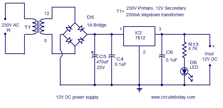
12V DC supply
12V DC power supply
A classic 12V regulated DC supply based on 7812 is shown above. A power ON indicator LED is also added in the circuit.Resistor R13 limits the LED current. A small aluminium heatsink can be fitted to the 7812 for better saftey.Small Al heatsinks for TO-220 package are readily available in the market

Touch Switch Circuit


Touch Switch Circuit using NE 555

Description

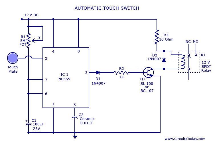
This is the circuit diagram of a small touch plate controller using IC NE 555 .This circuit is ideally useful for making touch operated doorbells, buzzers,toys etc which when touched on the touch plate operates the relay for a preset time and the turns off automatically.
This circuit is realized by utilizing the high input impedance of trigger pin of the 555 IC.When  the IC is triggered by the induced voltage of human body the output goes high for a time determined by R1 and C1.The transistor is used to drive the relay.The relay contacts can be used to drive the load like bell, motor , lights etc.

Notes.

To make the touch plate cut a 1 square cm thin metal sheet.
To setup the circuit connect to power supply and  adjust R1 while keeping touching on the touch plate.Stop at the point where relay activates.If relay is in the activated state initially then do the same until the relay is deactivated.

Touch Switch Circuit Diagram

touch switch circuit


Puff to OFF LED circuit.


Descrption.
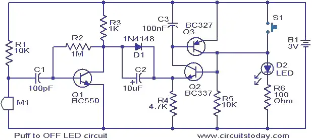
This is a simple circuit in which the glowing LED can be switched OFF just by a puff. A condenser mic (M1) is used to sense your puff. When the push button S1 is pressed, the transistors Q2 and Q3 wired as latching pair gets activated and drives the LED to glow. The LED remains in this condition. When you puff on the condenser mic, the sound pressure is converted into a voltage signal at its output. This voltage signal will be amplified by the transistor Q1.Since the collector of the Q1 is coupled to the emitter of the latching pair, the pair will stop conducting when ever there is a signal from the condenser mic due to puffing and the LED will go OFF.  The push button switch S1 has to be pressed again to switch the LED ON.
Circuit diagram with Parts list.
puff-top-off-led.JPG
Notes.
  • The circuit can be powered from a 3V battery.
  • The M1 can be a general purpose condenser microphone.
  • The switch S1 can be push button switch.
  • The circuit can be assembled on a good quality PCB or common board.
  • Instead of the LED, you can also try a low power 3V bulb

Low cost fire alarm circuit


Description.
When there is a fire breakout in the room the temperature increases.This ultra compact and low cost fire alarm senses fire breakout based on this fact.
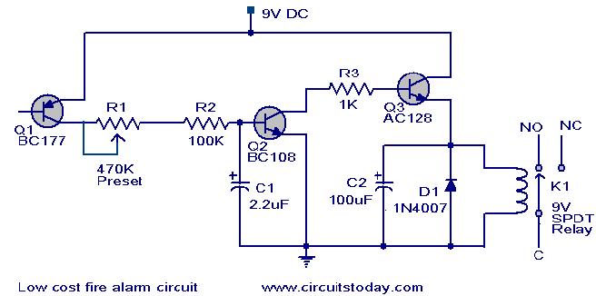
Transistor BC177 (Q1) is used as the fire sensor here.When the temperature increases the leakage current of this transistor also increases.The circuit is designed so that when there is an increase in the leakage current of Q1 ,transistor Q2 will get biased.As a result when there is a fire breakout the transistor Q2 will be on.The emitter of Q2 (BC 108)is connected to the base of Q3(AC 128).So when Q2 is ON Q3 will be also ON.The transistor Q3 drives the relay which is used to drive the load ie,light,bell,horn etc as an indication of the fire.The diode D1 is used as a free wheeling diode to protect it from back EMF generated when relay is switched.
Circuit diagram with Parts list.
fire-alarrm-circuit.JPG
Notes.
  • The Preset R1 can be used to desired temperature level for setting the alarm ON.
  • This is not a latching alarm,ie;when the temperature in the vicinity of the sensor decreases below the set point the alarm stops.
  • The circuit can be powered using  a 9V battery or a 9V battery eliminator.
  • All capacitors are electrolytic and must be rated at least 10V.
  • The load can be connected through the C,NC,NO points of the relay according to your need.
  • The calibration can be done using a soldering iron,and a thermo meter.Switch ON the power supply.Keep the tip of soldering iron near to the Q1.Same time also keep the thermometer close to it.When the temperature reaches your desired value adjust R1 so that relay gets ON.Done

Long duration timer circuit


Description.


This timer circuit can be used to switch OFF a particular device after around 35 minutes. The circuit can be used to switch OFF devices like radio, TV, fan, pump etc after a preset time of 35 minutes. Such a circuit can surely save a lot of power.
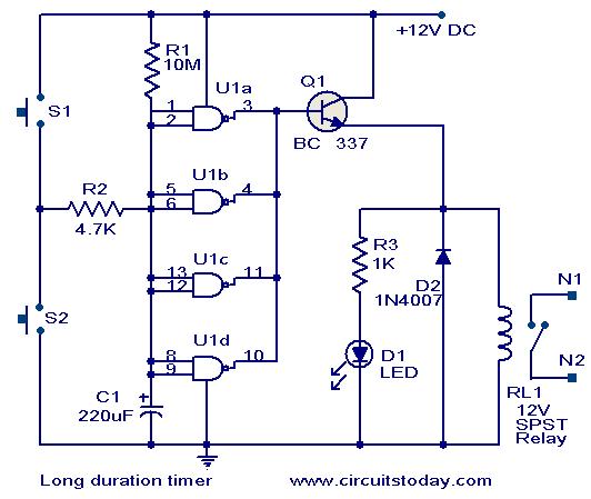
The circuit is based on quad 2 input CMOS IC 4011 (U1).The resistor R1 and capacitor C1 produces the required long time delay. When pushbutton switch S2 is pressed, capacitor C1 discharges and input of the four NAND gates are pulled to zero. The four shorted outputs of U1 go high and activate the transistor Q1 to drive the relay. The appliance connected via the relay is switched ON. When S2 is released the C1 starts charging and when the voltage at its positive pin becomes equal to ½ the supply voltage the outputs of U1 becomes zero and the transistor is switched OFF. This makes the relay deactivated and the appliance connected via the relay is turned OFF. The timer can be made to stop when required by pressing switch S1.

Circuit diagram with Parts list.


long-duration-timer-circuit.JPG
Notes.
  • Assemble the circuit on a good quality PCB or common board.
  • The circuit can be powered from a 9V PP3 battery or 12V DC power supply.
  • The time delay can be varied by varying the values of C1&R1.
  • The push button switch S2 is for starting the timer and S1 for stopping the time.
  • The appliance can be connected via contacts N1 & N2 of the relay RL1.
  • The IC U1 is 2 input quad NAND gate 4011

Shock alarm circuit


Description.
Here is a simple shock sensitive alarm circuit that has many many applications fro home to automobiles.The main application of this circuit is to use it as an anti theft alarm in automobiles.A peizo electric sensor is used as the shock sensor which has to mounted on the door which you have to protect.
Here the IC1  LM 3558 is wired as an inverting Schmitt Trigger.The POT R1 sets the threshold voltage of the circuit.R1 is used as a feed back resistor.When not activated the out put from the piezo sensor will be low and so do the output of the IC.When the piezo sensor is activated its output voltage goes high and triggers the Schmitt trigger.This results the beeping of the buzzer.The buzzer remains beeping for some time even if the vibration is removed.this is because the increase in the inverting input has little effect when the IC is triggered and the state can’t be easily reversed.
Circuit diagram with Parts list .
shock-alarm-circuit.JPG
Notes. 
  • A 3 v battery can be used as  power supply.
  • Fix the sensor firmly to the surface,where ever you place it.
  • It is always good to place the sensor near to the door knob.
  • Adjust R2 to obtain the required sensitivity.
  • Assemble the circuit on a good quality PCB or common board.
  • Use a IC holder for mounting the IC

Lamp flasher circuit


Description.
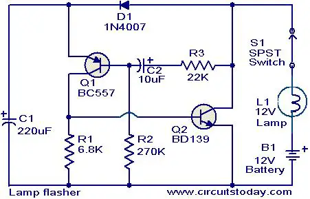
This simple circuit that can be used to flash incandescent lamps up to 10W power rating.The circuit is ideal for making flashing beacons on automobiles and other applications like that.The circuit is nothing but  an astable multi vibrator based on Q1&Q2 ( BC557&BD139).The capacitor C1 is the main timing element which determines the flashing rate of the circuit.The switch S1 can be used as an ON/OFF switch.
Circuit diagram with Parts list.
lamp-flasher-circuit.JPG
Notes. 
  • Power the circuit from a 12 V battery or 12V DC power supply.
  • Assemble the circuit on a goood quality PCB or common board.
  • A 12 v , 10W incandescent lamp can be used as the load.
  • All capacitors must be rated 15V

Page Rank

google pagerank

Write For Us

Submit a Guest Post

Find us on Facebook

Categories

555 Timer IC 7 segment Display 8051 Project AC Circuits Adafruit Alarms Amplifier Circuits Analog Circuits android Arduino arm processor Assembly Languange Atmel Atom Size Audio Circuits augmented reality Automotive Circuits avr Battery Circuits Bicycle Gurad bluetooth Cable TV Circuits Cambridge University Camera Technology Circuit Boards Clipping And Clamping Circuits Clocking And Timer Circuits Computing contact lens Contact Us Form Contests Controller Circuit Conversion Circuits Counter Circuits Digital Electronics diy circuits Downloads EFY EFYTimes Electronic Books Electronic Components Electronic Locks And Keys Engineering Fan Circuits Filter Circuits Fire Alarm free Frequency Fun And Game Circuits future Google Hack n Mod Ham Radio Circuits heart rate monitoring High Voltage Circuits Home Circuits IC Guide ieee Industrial Circuits Infrared Instructables Inventions ipad lcd Led Circuits Light Related Lighting Circuits Medical Circuits Meter Clocks Microcontrollers Microprocessors Mini Projects modules Movie maker NatGeo Navigation Notice Optical Fiber PC Circuits PCB Boards Physics pnp transistor Power Supplies Printing Projects Programmer Project Ideas Projectors Protection circuits Proximity Detectors Radar Radio Circuits Radio Transmitters Raspberry Raspberry Pie Remote Circuits Retis Lab RFID Robot Cars Robotics Science Science Alert Security And Safety Sensor Circuits Servo Motors Smallest Smartwatches sms Software solar cell sound application Spectram Switch Technology News Telephone Related Television Related Test And Measurement Circuits Thermal Projects Tone generator circuits Touch Screen Tutorials Wearables Wi-Fi Wireless
Like us on Facebook
Follow us on Twitter
Recommend us on Google Plus
Subscribe me on RSS