Search This Blog

Powered by Blogger.

Translate

Pyroelectric Fire Alarm System


This is definitely an ultra-sensitive fire sensor that exploits the direct piezoelectric property of an ordinary piezo component to recognize the fire. The lead zirconate titanate crystals within the piezo component have the property to deform and produce an electrical potential when heated, thus converting the piezo component into a heat sensor. The circuit mentioned right here is really sensitive. It provides a warning alarm in the event the area temperature raises over 10°C. The whole circuit has two modules: the sensor module and also the power supply module.

The Sensor circuit
The front end of the circuit contains a sensitive signal amplifier constructed close to IC1 (CA3130). It delivers a high output when temperature near the piezo component raises. IC CA3130 is really a CMOS operational amplifier with gate protected p-channel MOSFETs inside the inputs. It has high speed of operation and low input current specifications. There are certainly two inputs-the non-inverting input (pin 3) connected to the piezo component via diode D7 (OA71) that carries the voltage signal from the piezo component and the inverting input (pin 2) that gets a preset voltage through VR1.
By adjusting VR1, it is very easy to set the reference voltage level at pin 2. In normal condition, IC1 provides a low output and the remaining circuitry is within a standby state. Capacitor C2 keeps the non-inverting input of IC1 stable, so that even a slight change in voltage level in the inputs can change the output to high.
Typically, IC1 provides a low output, trying to keep transistor T1 non-conducting. Reseting pin 12 of IC2 (CD4060) connected to the collector of transistor T1 gets a high voltage via R5 and IC2 stays disabled. Once the piezo component gets heat from fire, asymmetry in its crystals causes a potential change, enabling capacitor C2 to discharge. It momentarily modifies the voltage level at pin 3 of IC1 and its output swings high. Transistor T1 conducts taking the reset pin 12 of IC2 to ground. IC2 is now enabled and gets going oscillating. With the shown values of the oscillating parts C3 (0.22ยต) and R6 (1M), the first output (Q3) turns high right after several seconds along with a red LED2 starts flashing. If heat near the piezo persists, Q7 (pin 14) output of IC2 becomes high after one minute, and also the alarm will start beeping. If heat continues, Q9 (pin 15) turns high after 4 minutes and turns on the relay driver transistor T2. Simultaneously, diode D8 conducts and IC2 stops oscillating and toggles.
The solenoid pump connected to the N/O (normally opened) contact of the relay starts spraying the fire-ceasing foam or water to the probable sites of fire.
The power supply circuit
Pyroelectric Fire Alarm System circuit
Power supply comprises a 0-12V, 1A step-down transformer having a standard full-wave rectifier formed by D1 through D4 and filter capacitor C1. A battery backup is supplied when the mains supply is cut-off because of short-circuit and fire. A 12V, 4.5Ah rechargeable battery is utilized for backup to provide enough current for the solenoid pump. When mains electrical power is available, diode D5 forward biases. It provides power towards the circuit and also charges the battery via resistor R2, and it limits the charging current to 120 mA. When power fails, diode D5 reverse biases and diode D6 forward biases, providing immediate backup for the circuit. LED1 signifies the availability of mains electrical power.
Assemble the circuit on a general purpose PCB and enclose it inside a appropriate case. Connect the piezo component to the circuit by using a thin insulated wire. Glue the flat side of the piezo component on a 30×30cm aluminium sheet to improve its sensitivity. Work on the sheet with the piezo sensor to the site in which protection is necessary. The remaining circuit could be fixed at a proper spot. If only the alarm generator is required, omit the relay driver section.
Download the circuit and explanation in PDF file: Pyroelectric Fire Alarm System

Low cost fire alarm circuit


Description.
When there is a fire breakout in the room the temperature increases.This ultra compact and low cost fire alarm senses fire breakout based on this fact.
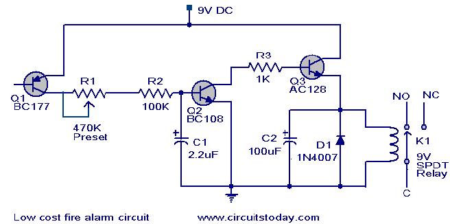
Transistor BC177 (Q1) is used as the fire sensor here.When the temperature increases the leakage current of this transistor also increases.The circuit is designed so that when there is an increase in the leakage current of Q1 ,transistor Q2 will get biased.As a result when there is a fire breakout the transistor Q2 will be on.The emitter of Q2 (BC 108)is connected to the base of Q3(AC 128).So when Q2 is ON Q3 will be also ON.The transistor Q3 drives the relay which is used to drive the load ie,light,bell,horn etc as an indication of the fire.The diode D1 is used as a free wheeling diode to protect it from back EMF generated when relay is switched.
Circuit diagram with Parts list.
fire-alarrm-circuit.JPG
Notes.
  • The Preset R1 can be used to desired temperature level for setting the alarm ON.
  • This is not a latching alarm,ie;when the temperature in the vicinity of the sensor decreases below the set point the alarm stops.
  • The circuit can be powered using  a 9V battery or a 9V battery eliminator.
  • All capacitors are electrolytic and must be rated at least 10V.
  • The load can be connected through the C,NC,NO points of the relay according to your need.
  • The calibration can be done using a soldering iron,and a thermo meter.Switch ON the power supply.Keep the tip of soldering iron near to the Q1.Same time also keep the thermometer close to it.When the temperature reaches your desired value adjust R1 so that relay gets ON.Done

Fire alarm circuit


Description.

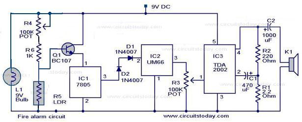
Here is a simple fire alarm circuit based on a LDR and lamp pair for sensing the fire.The alarm works by sensing the smoke produced during fire.The circuit produces an audible alarm when the fire breaks out with smoke.
When there is no smoke the light from the bulb will be directly falling on the LDR.The LDR resistance will be low  and so the voltage across it (below .6V).The transistor will be OFF and nothing happens.When there is sufficient smoke to mask the light from falling on LDR, the LDR resistance increases and so do the voltage across it.Now the transistor will switch to ON.This gives power to the IC1 and it outputs 5V.This powers the tone generator IC UM66 (IC2)  to play a music.This music will be amplified by IC3 (TDA 2002) to drive the speaker.Resistor R6 is meant for protecting the transistor when R4 is turned towards low resistance values .Resistor R2 and R1 forms a feedback network for the TDA2002 and C1 couples the feed back signal from the junction of R1 & R2 to the inverting input of the same IC.
The diode D1 and D2 in combination drops 1.4 V to give the rated voltage (3.5V ) to UM66 .UM 66 cannot withstand more than 4V.
Circuit diagram with Parts list.
fire alarm
Fire alarm circuit
Notes.
  • The speaker can be a 32ฮฉ tweeter.
  • POT R4 can be used to adjust the sensitivity of the alarm.
  • POT R3 can be used for varying the volume of the alarm.
  • Any general purpose NPN transistor(like BC548,BC148,2N222) can be used for Q1.
  • The circuit can be powered from a 9V battery or a 9V DC power supply.
  • Instead of bulb you can use a bright LED with a 1K resistor series to it.

Power supply for the circuit.

A well regulated power supply is essential for this circuit because even slight variations in the supply voltage could alter the biasing of the transistor used in the fire sensing section and this could seriously affect the circuit’s performance.
9V power supply
9V/500mA power supply circuit
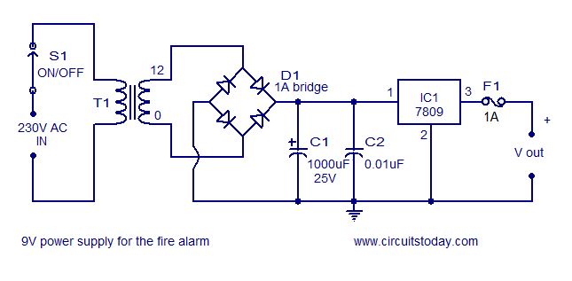
A regulated 9V/500mA power supply that can be used for powering the basic fire alarm circuit and its modified versions is shown above. Transformer T1 is a 230V primary, 12V secondary, 500mA step down transformer. D1 is a 1A bridge which performs the job of rectification. Capacitor C1 filters the rectifier output and C2 is the AC by-pass capacitor. IC1 (7809) is a 9V fixed positive voltage regulator. The output of the rectifier+filter section is connected to the input of 7805 and a regulated steady 9V is obtained at its output. S1 is the ON/OFF switch. F1 is a 500mA safety fuse.

Relay version of the circuit.

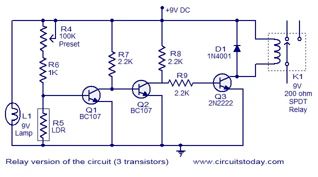
Here the above fire alarm circuit is modified to operate a relay when the fire breaks out. The usage of relay makes the circuit able to switch high power warning devices like alarms, bells,beacon lights etc that operates from the mains.
Relay version of the circuit
Two additional transistors are used with the basic fire sensing circuitry (consisting of Q1, R4, R5 and L1) to attain the target. Whenever the fire breaks out the transistor Q1 is switched ON. The collector voltage of Q1 drops to 0.2V and the transistor Q2 gets switched OFF. This makes the collector voltage of Q2 rise towards 9V and this result in the switching ON of transistor Q3. The relay connected at the collector of Q3 is activated and the load connected through the relay contact is driven. Resistors R7 and R8 limits the collector current of Q1 and Q2 respectively. D1 is a freewheeling diode which protects Q3 from the voltage spikes induced when the relay is switched. Resistor R9 controls the base current of transistor Q3 (2N2222)

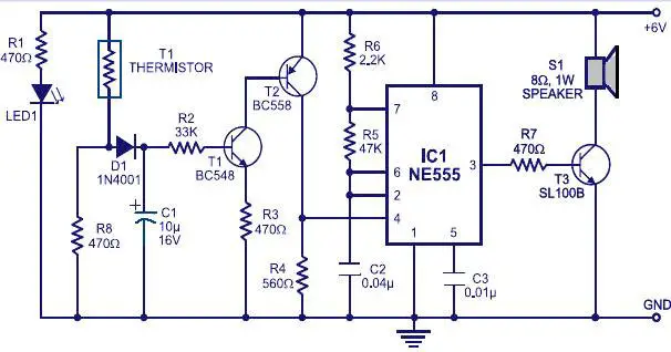
Fire alarm using thermistor & NE555


Description.
Many fire alarm circuits are presented here,but this time a new circuit using a thermistor and a timer to do the trick. The circuit is as simple and straight forward so that , it can be easily implemented.The thermistor offers a low resistance at high temperature and high resistance at low temperature. This phenomenon is employed here for sensing the fire.
The IC1 (NE555) is configured as a free running oscillator at audio frequency. The transistors T1 and T2 drive IC1. The output(pin 3) of IC1 is couples to base of transistor T3(SL100), which drives the speaker to generate alarm sound. The frequency of NE555 depends on the values of resistances R5 and R6 and capacitance C2.When thermistor becomes hot, it gives a low-resistance path for the positive voltage to the base of transistor T1 through diode D1 and resistance R2. Capacitor C1 charges up to the positive supply voltage and increases the the time for which the alarm is ON. The larger the value of C1, the larger the positive bias applied to the base of transistor T1 (BC548). As the collector of T1 is coupled to the base of transistor T2, the transistor T2 provides a positive voltage to pin 4 (reset) of IC1 (NE555). Resistor R4 is selected s0 that NE555 keeps inactive in the absence of the positive voltage. Diode D1 stops discharging of capacitor C1 when the thermistor is in connection with the positive supply voltage cools out and provides a high resistance path. It also inhibits the forward biasing of transistor T1.
Circuit diagram with Parts list.
fire-alarm-circuit.jpg
Notes.
  • The circuit can be powered from a 6V battery or a 6V power supply
  • The thermistor can be mounted on a heat resistant material like mica to prevent it from damage due to excessive heat.
  • The LED acts as an indication when the power supply is switched ON

Page Rank

google pagerank

Write For Us

Submit a Guest Post

Find us on Facebook

Categories

555 Timer IC 7 segment Display 8051 Project AC Circuits Adafruit Alarms Amplifier Circuits Analog Circuits android Arduino arm processor Assembly Languange Atmel Atom Size Audio Circuits augmented reality Automotive Circuits avr Battery Circuits Bicycle Gurad bluetooth Cable TV Circuits Cambridge University Camera Technology Circuit Boards Clipping And Clamping Circuits Clocking And Timer Circuits Computing contact lens Contact Us Form Contests Controller Circuit Conversion Circuits Counter Circuits Digital Electronics diy circuits Downloads EFY EFYTimes Electronic Books Electronic Components Electronic Locks And Keys Engineering Fan Circuits Filter Circuits Fire Alarm free Frequency Fun And Game Circuits future Google Hack n Mod Ham Radio Circuits heart rate monitoring High Voltage Circuits Home Circuits IC Guide ieee Industrial Circuits Infrared Instructables Inventions ipad lcd Led Circuits Light Related Lighting Circuits Medical Circuits Meter Clocks Microcontrollers Microprocessors Mini Projects modules Movie maker NatGeo Navigation Notice Optical Fiber PC Circuits PCB Boards Physics pnp transistor Power Supplies Printing Projects Programmer Project Ideas Projectors Protection circuits Proximity Detectors Radar Radio Circuits Radio Transmitters Raspberry Raspberry Pie Remote Circuits Retis Lab RFID Robot Cars Robotics Science Science Alert Security And Safety Sensor Circuits Servo Motors Smallest Smartwatches sms Software solar cell sound application Spectram Switch Technology News Telephone Related Television Related Test And Measurement Circuits Thermal Projects Tone generator circuits Touch Screen Tutorials Wearables Wi-Fi Wireless
Like us on Facebook
Follow us on Twitter
Recommend us on Google Plus
Subscribe me on RSS