Search This Blog

Powered by Blogger.

Translate

5 Microcontroller Based Projects You Must Not Miss!

Looking for a microcontroller based project? From our collection of microcontroller based projects, we bring to you 5 super cool projects. Have fun!


A tachometer is nothing but a simple electronic digital transducer. Normally, it is used for measuring the speed of a rotating shaft. The number of revolutions per minute (rpm) is valuable information for understanding any rotational system. For example, there is an optimum speed for drilling a particular-size hole in a particular metal piece; there is an ideal sanding disk speed that depends on the material being finished. You may also want to measure the speed of fans you use.

Here is an easy-to-construct temperature indicator-cum-controller that can be interfaced with a heater coil to maintain the ambient room temperature. The controller is based on Atmega8535 microcontroller, which makes it dynamic and faster, and uses an LCD module to display and two keys to increase or decrease the set values.

Digital wall clocks, table clocks and desk clocks with pointer or LCD display are readily available in the market. Here we present a clock that can be built in a small budget using AT89C2051 microcontroller. Additional feature of the clock is that the time display is visible even in the dark.

Microcontroller-based embedded systems play major role in industrial automation. One such widely used system is the programmable timer.

The circuit that uses microcontroller AT89C51 can control four devices from a distance of upto 30 metres wirelessly. An LCD module is used to show the device number and preset control time at the transmitter module.

Source: http://electronicsforu.com/

$20 Robot From MIT Wins AFRON Design Challenge Made From Arduino Board


Robots, as anyone who has ever attempted to build or buy or fix a robot knows, tend to be expensive. This presents a problem for people who want to start learning about robotics, because getting a foot in the door with an actual robot to work on generally involves a substantial up-front investment in hardware. And for places where teachers and students don't have huge piles of money to throw at technology, this can mean that robots just don't happen.
The African Robotics Network (AFRON) and IEEE Robotics and Automation Society (RAS) collectively sponsor a biennial design challenge to "collaboratively create an educational robot that is an order of magnitude less expensive than existing products, to inspire young people around the world." For 2013/2014, MIT took home a win with their MIT SEG robot, a 3D-printed, Arduino-based wheeled robot that can be built for $20 in five steps with no training or tools.
The completed MIT SEG is shown in the picture above; below is an image of the unassembled robot in its entirety:
All you have to do to go from this to robot is fold up the chassis (the squareish bits at the lower left), fold the wheels together, fit the electronics in, stick the wheels onto the servos, and that's it, you're done. Here's the bill of materials:
MIT points out that if you don't go with a breakout board for the Arduino and instead wire-wrap the headers directly, you can drop the cost by about $2.50 per bot. You also need a programmer and a charger, which together will run you another $18.20, but these can be shared among multiple robots.
So great, you've got a robot that's easy to make and is dirt cheap. What can it do? Out of the box, MIT SEG includes an Arduino compatible drag-and-drop graphical programming interface. The LED and photosensor can be used to determine whether the robot is looking at something black, white, or gray, meaning that you can do line-following and some obstacle avoidance right away, and MIT has put together a bunch of examples and an entire curriculum that classrooms can follow. Plus, since the robot has an Arduino for a brain, you can leverage all of the hardware (and the community) that's been plugging into Arduinos for the last few years.
Second place in the hardware portion of the Design Challenge went toHarvard's $10.70 AERobot:
The Ultra Affordable Educational Robot Project Design Challenge also includes categories for Software, Curriculum, and Community Challenges.
"The AFRON organizers and RAS sponsors admire the ingenuity of the submissions in all categories," said Ken Goldberg, a roboticist at UC Berkeley who co-founded AFRON with Ayorkor Korsah, a professor of computer science at Ashesi University, in Ghana. Goldberg noted that two winning projects from Africa, PanyaBot (Kenya) and ARX LollyBot (Ghana), continue to make major advances in the Software and Community Challenge categories. "We look forward to connecting all the participants to share ideas and designs for next steps via the AFRON network, which anyone worldwide can join at no cost," he said.

Source : http://spectrum.ieee.org/automaton/robotics/diy/20-robot-mit-wins-afron-design-challenge

Piccolo – The ‘Sketching’ Robot

Piccolo

Piccolo can be said as the perfect companion for a graphic designer or an engineer as it helps him to sketch his creativity. Piccolo is a small pocket sized robot which uses servo mechanism for developing and deploying the accurate 2D or 3D output. Like all other robots, this one also works according to CNC technology. CNC is the acronym of Computer Numerical Control. Here the computer converts the design produced by the computer aided design software (CAD) into numbers. These numbers denote different coordinates – that is X, Y and Z in a graph. This technology is employed in a number of places such as the automatic machine cutting, or the drawing tool.  We can sketch a simple drawing or cut a sheet using a laser tip by attaching the corresponding tip to this bot. Piccolo will work according to the type of tip attached to it. Another important advantage of Piccolo is its portability. We can carry this cool machine anywhere with us. When compared to other CNC based robots, this one does not cost thousands of dollars but just $70.This device was introduced by the Diatom studio from London with the collaboration of Cheng  Xu and Huaishu Peng  From CoDe Lab.
Piccolo Demonstration Video
 Piccolo is open source – anyone can modify its design. The prototype is simple; it can be assembled quickly and is easy to use. The Piccolo includes Arduino and processing libraries so that we can use Piccolo as we wish like moving automatically or by responding to a sensor. We can engage multiple piccolos to work together so that it could create a larger canvas. In the Piccolo kit we are provided with the facility to create 3D or 2D sketches according to our desire.

Source: http://www.circuitstoday.com/piccolo-the-%E2%80%98sketching%E2%80%99-robot

[TC] Remote controlled Spy Bot

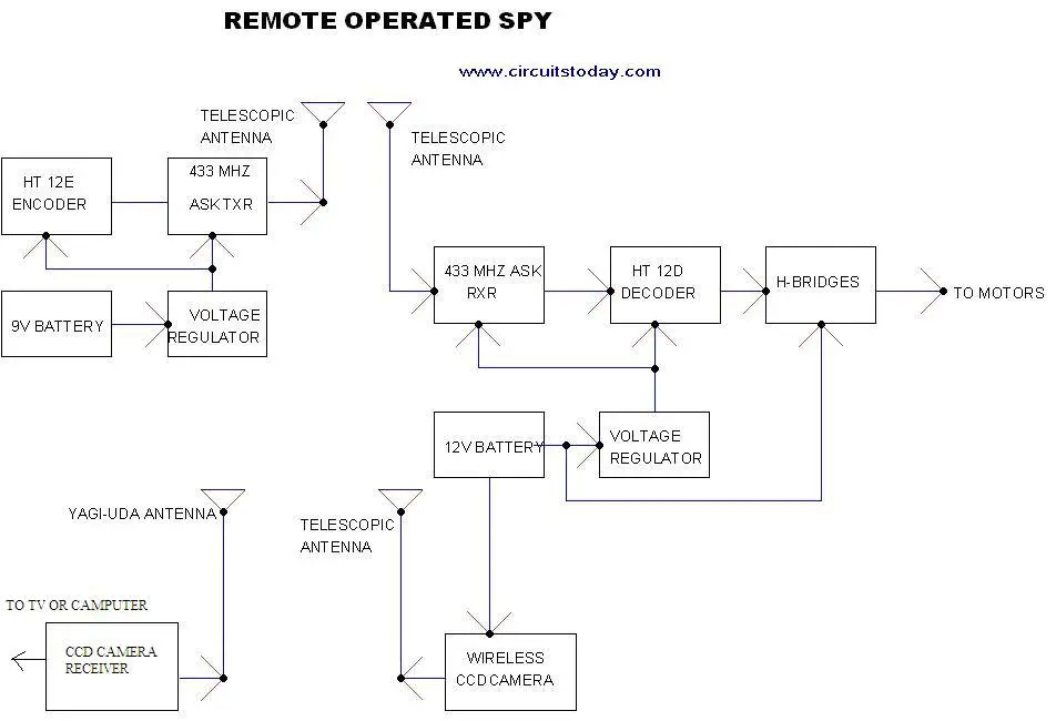
Here is a remote operated spy robot circuit which can be controlled by using a wireless remote controller. It can capture audio and video information’s from the surroundings and can be sent to a remote station through RF signals. The maximum range is 125 meters. It overcomes the limited range of infrared remote controllers. This robot consists of mainly two sections. They are explained in detail below.

Remote Control Operated Spy Robot Circuit – Block Diagram

    Remote Control Operated Spy Robot Circuit - Block Diagram
Remote Control Operated Spy Robot Circuit - Block Diagram

1. Remote Control Section

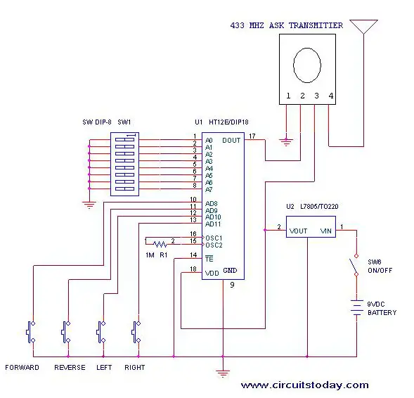
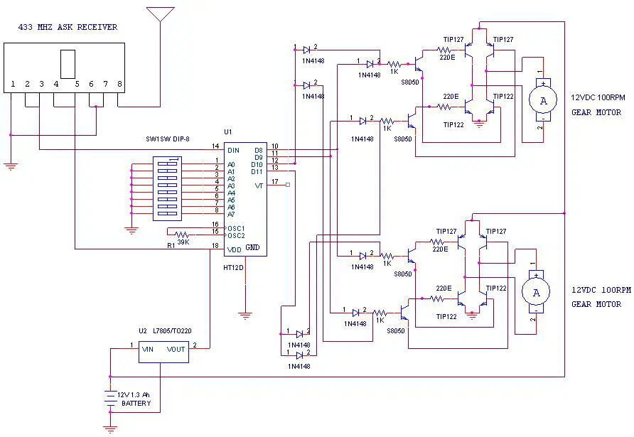
The circuit uses HT 12E, HT 12D encoder and decoder. 433MHz ASK transmitter and receiver is used for the remote control. H-bridge circuits are used for driving motors. Two 12V DC/100RPM gear motors are used as drivers. The working of the circuit is as follows.
When we are pressing any key in remote controller the HT 12E generate 8 bit address and 4 bit data .The DIP switches are used for setting the address. Then the ASK transmitter sends the 8 bit address and 4 bit data to the receiver Then the ASK receiver receives the 8 bit address and 4 bit data and HT 12D decoder decodes the data, thus enabling the appropriate output. Thus the output signals that are generated controls the H-bridge which then rotates the motors.
The 433 MHZ ASK transmitter and receivers are extremely small, and are excellent for applications requiring short-range RF remote controls.  The transmitter module is only 1/3rd the size of a standard postage stamp, and can easily be placed inside a small plastic enclosure. The transmitter output is up to 8mW at 433.92MHz. The transmitter accepts both linear and digital inputs and can operate from 1.5 to 12 Volts-DC, and makes building a miniature hand-held RF transmitter very easy.  The 433 MHZ ASK transmitters is approximately the size of a standard postage stamp
433 MHZ ASK receivers also operate at 433.92MHz, and have a sensitivity of 3uV.  The receiver operates from 4.5 to 5.5 volts-DC.
Remote-Control-Operated-Spy-Robot-Circuit-Remote-Control-Section

2. Video Transmission Section

In this project we are using a wireless CCD camera. Now these types of cameras are commonly available in the market. It works on 12VDC supply.


The 12 Volt DC supply is taken from the battery placed in the robot. The camera has a receiver, which is placed in the remote station. Its output signals are in the form of audio and video. These signals are directly connected to a TV receiver or a computer through a tuner card.
Remote Operated Spy Robot - Remote Control Section

Components Required

IC HT 12E 1
HT 12D 1

LM 7805 2
TRANSISTOR TIP 127 4

TIP 122 4

S 8050 4
DIODE 1N 4148 8
RESISTOR 1K 4

220E 4

39K 1

1M 1
ASK TRANSMITTER 433 MHz 1
ASK RECEIVER 433 MHz 1
DIP SWITCH
2
PUSH TO ON SWITCH
4
GEAR MOTOR 12V DC 100rpm 2
BATTERY 12V 1.3 Ah   rechargeable 1

9V 1
WIRELESS CCD CAMERA
1

Construction

The steps for the construction are…
1. Take a hylam sheet with (20cm*15cm) size.
2. Fix two gear motors (12VDC 100rpm) in the hylam sheet by using aluminum pieces and nut bolts as shown in the figure below.
3. Fix the ball castor as shown in the figure below.
Construction of Remote Operated Spy Robot Circuit
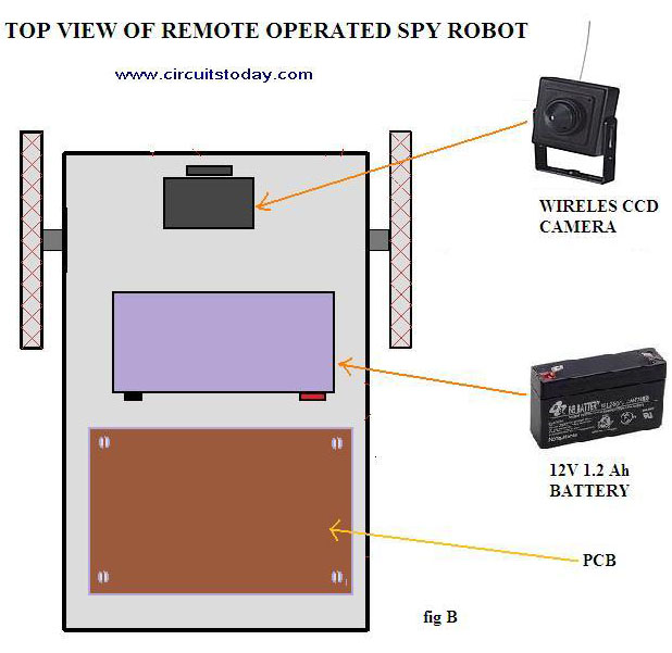
4. Then fix the battery (12VDC 1.2Ah) on the top of the spy robot as shown in the figure below.
Construction of Remote Operated Spy Robot Circuit - Top View
Construction of Remote Operated Spy Robot Circuit – Top View
5. Connect two motors to the PCB. The PCB is then connected to the battery.
6. Connect the wireless CCD camera to the battery.
7. Connect the camera receiver to the TV or computer. Video information’s will thus appear in the screen.
8. Switch on the remote controller and control the spy robot


Source: http://www.circuitstoday.com/

Page Rank

google pagerank

Write For Us

Submit a Guest Post

Find us on Facebook

Categories

555 Timer IC 7 segment Display 8051 Project AC Circuits Adafruit Alarms Amplifier Circuits Analog Circuits android Arduino arm processor Assembly Languange Atmel Atom Size Audio Circuits augmented reality Automotive Circuits avr Battery Circuits Bicycle Gurad bluetooth Cable TV Circuits Cambridge University Camera Technology Circuit Boards Clipping And Clamping Circuits Clocking And Timer Circuits Computing contact lens Contact Us Form Contests Controller Circuit Conversion Circuits Counter Circuits Digital Electronics diy circuits Downloads EFY EFYTimes Electronic Books Electronic Components Electronic Locks And Keys Engineering Fan Circuits Filter Circuits Fire Alarm free Frequency Fun And Game Circuits future Google Hack n Mod Ham Radio Circuits heart rate monitoring High Voltage Circuits Home Circuits IC Guide ieee Industrial Circuits Infrared Instructables Inventions ipad lcd Led Circuits Light Related Lighting Circuits Medical Circuits Meter Clocks Microcontrollers Microprocessors Mini Projects modules Movie maker NatGeo Navigation Notice Optical Fiber PC Circuits PCB Boards Physics pnp transistor Power Supplies Printing Projects Programmer Project Ideas Projectors Protection circuits Proximity Detectors Radar Radio Circuits Radio Transmitters Raspberry Raspberry Pie Remote Circuits Retis Lab RFID Robot Cars Robotics Science Science Alert Security And Safety Sensor Circuits Servo Motors Smallest Smartwatches sms Software solar cell sound application Spectram Switch Technology News Telephone Related Television Related Test And Measurement Circuits Thermal Projects Tone generator circuits Touch Screen Tutorials Wearables Wi-Fi Wireless
Like us on Facebook
Follow us on Twitter
Recommend us on Google Plus
Subscribe me on RSS