Search This Blog

Powered by Blogger.

Translate

$20 Robot From MIT Wins AFRON Design Challenge Made From Arduino Board


Robots, as anyone who has ever attempted to build or buy or fix a robot knows, tend to be expensive. This presents a problem for people who want to start learning about robotics, because getting a foot in the door with an actual robot to work on generally involves a substantial up-front investment in hardware. And for places where teachers and students don't have huge piles of money to throw at technology, this can mean that robots just don't happen.
The African Robotics Network (AFRON) and IEEE Robotics and Automation Society (RAS) collectively sponsor a biennial design challenge to "collaboratively create an educational robot that is an order of magnitude less expensive than existing products, to inspire young people around the world." For 2013/2014, MIT took home a win with their MIT SEG robot, a 3D-printed, Arduino-based wheeled robot that can be built for $20 in five steps with no training or tools.
The completed MIT SEG is shown in the picture above; below is an image of the unassembled robot in its entirety:
All you have to do to go from this to robot is fold up the chassis (the squareish bits at the lower left), fold the wheels together, fit the electronics in, stick the wheels onto the servos, and that's it, you're done. Here's the bill of materials:
MIT points out that if you don't go with a breakout board for the Arduino and instead wire-wrap the headers directly, you can drop the cost by about $2.50 per bot. You also need a programmer and a charger, which together will run you another $18.20, but these can be shared among multiple robots.
So great, you've got a robot that's easy to make and is dirt cheap. What can it do? Out of the box, MIT SEG includes an Arduino compatible drag-and-drop graphical programming interface. The LED and photosensor can be used to determine whether the robot is looking at something black, white, or gray, meaning that you can do line-following and some obstacle avoidance right away, and MIT has put together a bunch of examples and an entire curriculum that classrooms can follow. Plus, since the robot has an Arduino for a brain, you can leverage all of the hardware (and the community) that's been plugging into Arduinos for the last few years.
Second place in the hardware portion of the Design Challenge went toHarvard's $10.70 AERobot:
The Ultra Affordable Educational Robot Project Design Challenge also includes categories for Software, Curriculum, and Community Challenges.
"The AFRON organizers and RAS sponsors admire the ingenuity of the submissions in all categories," said Ken Goldberg, a roboticist at UC Berkeley who co-founded AFRON with Ayorkor Korsah, a professor of computer science at Ashesi University, in Ghana. Goldberg noted that two winning projects from Africa, PanyaBot (Kenya) and ARX LollyBot (Ghana), continue to make major advances in the Software and Community Challenge categories. "We look forward to connecting all the participants to share ideas and designs for next steps via the AFRON network, which anyone worldwide can join at no cost," he said.

Source : http://spectrum.ieee.org/automaton/robotics/diy/20-robot-mit-wins-afron-design-challenge

Tutorial: Making Solar Cell Using 2N3055 Transistor


This video unveils the fact that a silicon diode is quite similar to a solar cell. To prove this, it takes apart a 2N3055 power transistor to produce 1.6 milliwatts. Watch the video for a great tutorial on creating a transistor solar cell.

It's easy to cut open a power transistor like the 2N3055 to expose the NPN silicon material inside to make a solar cell. When exposed to sunlight, or household lights, it conducts electricity. The N-type and P-type materials work like a solar cell. The best way is from the Base to the Collector though from both the Base and Emitter combined and then to the Collector also works well. The voltage and current aren't much but with just a few of them in series you can power a small 1.5 volt calculator.


Source: http://electronicsforu.com/newelectronics/video/detailvideo.asp?id=2077

Stereo FM transmitter

PLL Stereo FM transmitter circuit.

BH1417 IC

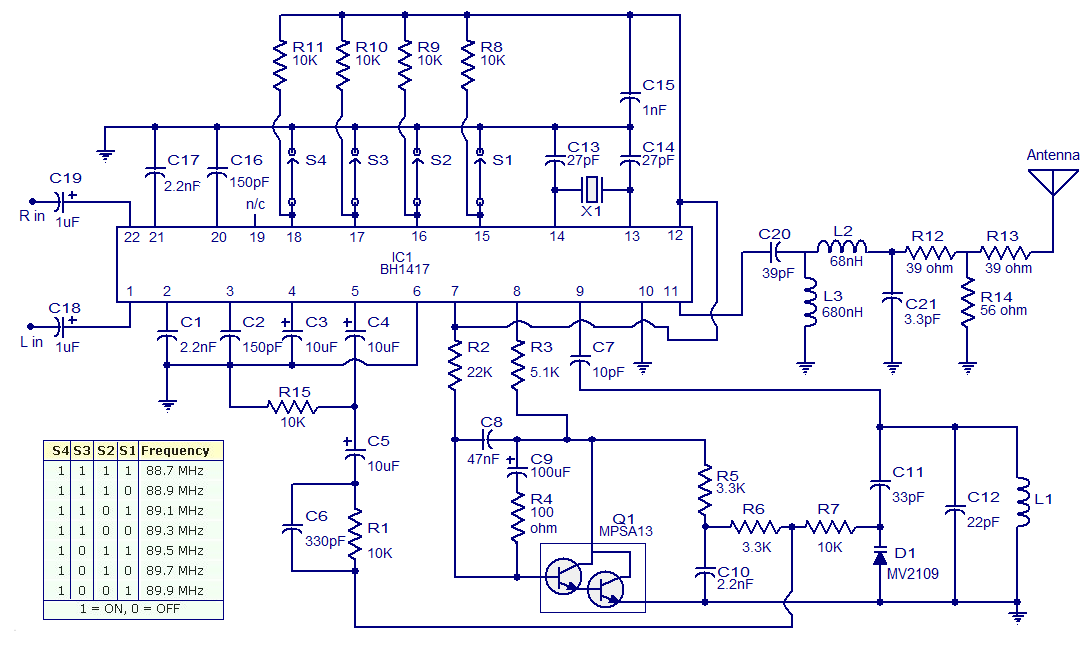
The circuit shown here is of a good Stereo FM transmitter that can transmit high quality signals up to a range of 70 feet. The circuit is based on BH1417 PLL stereo transmitter IC from Rhom semiconductors. The IC has separate audio processing sections for the left and right channels, pre emphasis circuit for improving signal to noise ratio, crystal control circuitry for accurate frequency locking, multiplex circuit for making sum ( left plus right) and difference ( left minus right) {see this article for better understanding Stereo decoder circuit} etc. Another important feature of this IC is that the transmission frequency can be set using a 4 channel DIP switch. The IC can be powered from anything between 4 to 6V DC and has an output power around 20mW. At full output power the circuit consumes only 20mA and has a channel separation of 40dB.There are 14 possible preset transmission frequencies, starting from 88.7MHz and incrementing in steps of 0.2MHz that can be selected using the DIP switch. The PLL circuitry of the IC is so precise that there is practically no frequency drift.

Circuit diagram.

BH1417 FM transmitter circuit
Stereo FM transmitter circuit using BH1417

Circuit description.

Capacitors C18 and C19 are DC decoupling capacitors for the left and right channel inputs. Capacitors C1 and C17 are used to set the amount of pre-emphasis required and here with the used values it is 50uS. Capacitors C2 and C16 sets the roll-off point of the low pass filter. The crystal X1 is a 7.6MHz crystal which sets the oscillator’s frequency while capacitors C13 and C14 associated with are used for providing the appropriate loading. Resistors R8 to R11 are the pull-up resistors for the D0 to D3 (pins 15 to 18 of the IC) respectively. These pins can be held low by closing the corresponding switches. The RF oscillator of the IC is tuned using the components L1, C11, C12 and D1. Capacitor C11 prevents and DC voltage being applied to the varicap diode D1 and thereby prevents current flow into the inductor L1. More over it reduces the effects of changes in the capacitance of D1 on the pin 9. Capacitor C7 prevents any DC current from flowing into the inductor L1 from pin 9 of the IC. The composite output signal at pin 5 is applied to the junction of R6 and R7 though a network comprising of components C4, C5, C6 and R1. In the circuit pin 19 of the circuit is left unconnected, but an optional capacitor at this pin can be used to set the pilot level and phase. Any way such a capacitor is not at all a necessity here and the circuit will work perfectly even if the capacitor at pin 9 is omitted.
The composite output signal undergoes some attenuation while passing through this network and finally reaches the varicap diode D1. The carrier frequency is controlled using the PLL (phase lock loop) phase detector output pin (pin 7) and the components connected around it. The darlington transistor Q1 is driven by the output of the pin7 and the transistor applies a control voltage on the varicap diode through resistor R5, R6 and R7. Capacitor C10 works as a high frequency filter while R7 is meant for isolation. Resistor R4 and capacitor C9 connected in series between the collector and base of Q1 provides further filtering. Resistor R4 improves the response of the transistor to transient changes while capacitor C9 improves low frequency filtering. Capacitor C8 connected between collector and base of Q1 provides additional high frequency filtering. Resistor R3 serves as the collector load for the transistor Q1.
The modulated RF output is available at pin 11 and it is fed to the antenna through a filter network consisting of components L2, L3, C20, and C21. The job of this filter network is to remove harmonics. Resistors R12, R13 and R14 reduces the signal level to the antenna and as a result decreases the output power of the transmitter. Such a reduction is necessary to make the transmitter legal because in many countries transmitters that has an output power more than few milli watts (may change from nation to nation) are illegal. By omitting R12, R13, R14 and connecting the antenna directly to the junction of L2 and C21, the range can be increased, but do it at your own risk.

Setting up the transmitter.

Firstly set the frequency of transmission using the DIP switch. Then connect the circuit to the power supply and connect the positive lead of your multimeter to pin 8 of the IC and the negative lead to ground. The multimeter should show a reading equal to the supply voltage. Now move the positive lead of the multimeter to the junction of R5 and R6 and adjust the slug (ferrite core of L1) so that the multimeter reads 2V. The L1 has to be readjusted for getting 2V between junction of R5, R6 and Ground every time you change the transmission frequency.

Notes.

  • Assemble the circuit on a good quality PCB.
  • The circuit can be powered from anything between 4 to 6V DC. I recommend using a 6V battery pack.
  • If you are using a battery eliminator for powering the circuit, it must be well regulated and free of any sort of noise.
  • Antenna can be a 1 metre long insulated copper wire.
  • Table for selecting the frequency is shown with the circuit diagram.
  • Crystal X1 is 7.68MHz.
  • For L1 make 2.5 turns of 1mm enamelled copper wire on a plastic former with an F29 ferrite slug inside it.
  • Optional 10K POTs can be connected in series to the input pins (pins 22 and 1) of the IC for adjusting the channel balance.
  • All electrolytic capacitors are rated at 10V DC.

FM adaptor circuit for car stereo


Description.
With this compact FM adaptor circuit plugged into the audio out of your cassete player or i Pod out put,you can listen your favorite music on your car stereo.This circuit is very useful if your car stereo doesnot have an auxillary in socket.The circuit is nothing buy  an short range  FM transimitter.
The FM transmitter circuit is based on low power NPN transistor 2N2222.The tank circuit consisting of L1 & C1 producess the necessary oscillations at the collector of Q1.The capacitance C4 , resistance R3 & R4  performs the function of mixing the stereo out put from theaudio player or i-Pod.The emitter resistance R2 provides sufficient stability to the circuit.It also limits the collector current to increse the battery life.
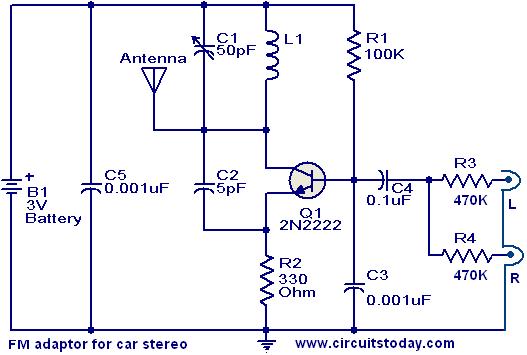
Circuit diagram with Parts list.


fm-adaptor-circuit-for-car-stereo.JPG
Notes.
  • Use a 28SWG , 10 cm insulated copper wire as antenna.
  • For L1.make 8 turns of 20 SWG insulated copper wire on a 5mm dia plastic former.
  • Power the circuit from a 3V battery.
  • Assemble the circuit on a good quality PCB or common board.
  • C1 can be a  50pF trimmer

Page Rank

google pagerank

Write For Us

Submit a Guest Post

Find us on Facebook

Categories

555 Timer IC 7 segment Display 8051 Project AC Circuits Adafruit Alarms Amplifier Circuits Analog Circuits android Arduino arm processor Assembly Languange Atmel Atom Size Audio Circuits augmented reality Automotive Circuits avr Battery Circuits Bicycle Gurad bluetooth Cable TV Circuits Cambridge University Camera Technology Circuit Boards Clipping And Clamping Circuits Clocking And Timer Circuits Computing contact lens Contact Us Form Contests Controller Circuit Conversion Circuits Counter Circuits Digital Electronics diy circuits Downloads EFY EFYTimes Electronic Books Electronic Components Electronic Locks And Keys Engineering Fan Circuits Filter Circuits Fire Alarm free Frequency Fun And Game Circuits future Google Hack n Mod Ham Radio Circuits heart rate monitoring High Voltage Circuits Home Circuits IC Guide ieee Industrial Circuits Infrared Instructables Inventions ipad lcd Led Circuits Light Related Lighting Circuits Medical Circuits Meter Clocks Microcontrollers Microprocessors Mini Projects modules Movie maker NatGeo Navigation Notice Optical Fiber PC Circuits PCB Boards Physics pnp transistor Power Supplies Printing Projects Programmer Project Ideas Projectors Protection circuits Proximity Detectors Radar Radio Circuits Radio Transmitters Raspberry Raspberry Pie Remote Circuits Retis Lab RFID Robot Cars Robotics Science Science Alert Security And Safety Sensor Circuits Servo Motors Smallest Smartwatches sms Software solar cell sound application Spectram Switch Technology News Telephone Related Television Related Test And Measurement Circuits Thermal Projects Tone generator circuits Touch Screen Tutorials Wearables Wi-Fi Wireless
Like us on Facebook
Follow us on Twitter
Recommend us on Google Plus
Subscribe me on RSS