Search This Blog

Powered by Blogger.

Translate

Infrared Illuminator Made With LEDs

Figure:1

Figure 1 

As infrared LED array came up with technology and state of the art electronic and optical components that will bring us the ultimate in day and night vision efficiency and high power infrared output.
This can be started by calculating how much infrared radiation you will need in order to light your scene that would be the focal range of your camera since details are lost on most security cameras. With the use of Dremel tool or small bench top grinder, grind down one side of the LEDs slightly and then pack them down to a smaller area. The builder used 19 by 13 LEDs for a total of 247 LEDs, to fit into the inside of a halogen work light.
When the LED array is wired, simply run copper wire along the columns to create the parallel wiring connection for each series chain. The power adapter can be plugged into an AC socket just as it was before modification and cut the AC wiring inside the light enclosure and affixed it directly to the AC power adapter. Materials such as dark tinted glass will also work to conceal an LED array.

To see the rest of the project, go to <http://www.lucidscience.com/pro-led array illuminator-1.aspx>

[TC] Automatic Street Light

Introduction:
Needs no manual operation for switching ON and OFF. When there is need of light it automatically switches ON. When darkness rises to a certain value then sensor circuit gets activated and switches ON and when there is other source of light i.e. day time, the street light gets OFF. The sensitiveness of the street light can also be adjusted. In our project we have used four L.E.D for indication of bulb but for high power switching one can connect Relay (electromagnetic switch) at the output of pin 3 of I.C 555. Then it will be possible to turn ON/OFF any electrical appliances connected all the way through relay.

                        Automatic Street Light
Principle :
This circuit uses a popular timer I.C 555. I.C 555 is connected as comparator with pin-6 connected with positive rail, the output goes high(1) when the trigger pin 2 is at lower then 1/3rd level of the supply voltage. Conversely the output goes low (0) when it is above 1/3rd level. So small change in the voltage of pin-2 is enough to change the level of output (pin-3) from 1 to 0 and 0 to 1. The output has only two states high and low and can not remain in any intermediate stage. It is powered by a 6V battery for portable use. The circuit is economic in power consumption. Pin 4, 6 and 8 is connected to the positive supply and pin 1 is grounded. To detect the present of an object we have used LDR and a source of light. LDR is a special type of resistance whose value depends on the brightness of the light which is falling on it. It has resistance of about 1 mega ohm when in total darkness, but a resistance of only about 5k ohms when brightness illuminated. It responds to a large part of light spectrum. We have made a potential divider circuit with LDR and 100K variable resistance connected in series. We know that voltage is directly proportional to conductance so more voltage we will get from this divider when LDR is getting light and low voltage in darkness. This divided voltage is given to pin 2 of IC 555. Variable resistance is so adjusted that it crosses potential of 1/3rd in brightness and fall below 1/3rd in darkness.
Sensitiveness can be adjusted by this variable resistance. As soon as LDR gets dark the voltage of pin 2 drops1/3rd of the supply voltage and pin 3 gets high and LED or buzzer which is connected to the output gets activated.

Automatic Street Light Circuit Diagram
                        Circuit Diagram of Automatic Street Light

Component used :
9v Battery with strip
Switch
L.D.R (Light Depending Resistance)
I.C NE555 with Base
L.E.D (Light Emitting Diode) 3 to 6 pieces.
Variable Resistance of 47 Kilo ohms
P.C.B (Printed Circuit Board of 555 or Vero board.

COMPONENTS :
a) Battery: For 9v power supply we can use 6pcs dry cell or 6F22 9v single piece battery.
b)Switch:Any general purpose switch can be used. Switch is used as circuit breaker.
c) L.D.R: (Light Depending Resistance)
it is a special type of resistance whose value depends on the brightness of light which is falling on it. It has resistance of about 1mega ohm when in total darkness, but a resistance of only about 5k ohms when brightness illuminated. It responds to a large part of light spectrum.
d) L.E.D: (Light Emitting Diode)
A diode is a component that only allows electricity to flow one way. It can be 
thought as a sort of one way street for electrons. Because of this characteristic, diode are used to transform or rectify AC voltage into a DC voltage. Diodes have two connections, an 
anode and a cathode. The cathode is the end on the schematic with the point of the triangle pointing towards a line. In other words, the triangle points toward
that cathode. The anode is, of course, the opposite end. Current flows from the anode to the cathode. Light emitting diodes, or LEDs, differ from regular diodes in that when a voltage is applied, they emit light. This light can be red (most common), green, yellow, orange, blue (not very common), or infa red. LEDs are used as indicators, transmitters, etc. Most likely, a LED will never burn out like a regular lamp will and requires many times less current. Because LEDs act like regular diodes 
and will form a short if connected between + and -, a current limiting resistor is used to prevent that very thing. LEDs may or may not be drawn with the circle surrounding them.
e) Variable resistance: (Potentiometer)
Resistors are one of the most common electronic components. A resistor is a device that limits, or resists current. The current limiting ability or resistance is measured in ohms, represented by the Greek symbol Omega. Variable resistors (also called potentiometers or just "pots") are resistors that have a variable resistance. You adjust the resistance by turning a shaft. This shaft moves a wiper across the actual resistor element. By changing the amounts of resistor between the wiper connection and the connection (s) to the resistor element, you can change the resistance. You will often see the resistance of resistors written with K (kilohms) after the number value. This means that there are that many thousands of ohms. For example, 1K is 1000 ohm,2K is 2000 ohm, 3.3K is 3300 ohm, etc. You may also see the suffix M (mega ohms). This simply means million. Resistors are also rated by their power handling capability. This is the amount of heat the resistor can take before it is destroyed. The power capability is measured in W (watts) Common wattages for variable
resistors are 1/8W, 1/4W, 1/2W and 1W. Anything of a higher wattage is referred to as a rheostat
f) PCB (Printed Circuit Board)
with the help of P.C.B it is easy to assemble circuit with neat and clean end products. P.C.B is made of Bakelite with surface pasted with copper track-layout. For each components leg, hole is made.
Connection pin is passed through the hole and is soldered.
WORKING:
When light falls on the LDR then its resistance decreases which results in increase of the voltage at pin 2 of the IC 555. IC 555 has got comparator inbuilt, which compares between the input voltage from pin2 and 1/3rd of the power supply voltage. When input falls below 1/3rd then output is set high otherwise it is set low. Since in
brightness, input voltage rises so we 
obtain no positive voltage at output of pin 3 to drive relay or LED, besides in poor light condition we get output to energize.
Precautions:
a) Use a Sensitive LDR. Before using it should be tested with multimeter.
b) I.C should not be heated too much while soldering, can destroy the I.C. For safety and easy to replace, use of I.C base is suggested. While placing the I.C pin no 1 should be made sure at right hole.
c) Opposite polarity of battery can destroy I.C so please check the polarity before switching ON the circuit. One should use diode in series with switch for safety since diode allows flowing current in one direction only.
d) L.E.D glows in forward bias only so incorrect polarity of L.E.D will not glow. Out put voltage of our project is 7.3 volt therefore 4 LED in series can be easily used with out resistance.
e) Each component should be soldered neat and clean. We should check for any dry soldered.
f) LDR should be so adjusted that it should not get light from streetlight itself.

[TC] Multiutility flash light


Multiutility flash light  


This multiutility flash light consists of three sections: a flasher, a sound-to-light display and a white LED-based flashlight.

The flasher circuit (Fig. 1) is built around an NE555 timer IC that is wired as an astable multivibrator. It flashes a pair of LEDs alternatively. The frequency of the astable multivibrator can be varied using preset VR1.


Fig. 1: Flasher circuit  
The working of the sound-to-light display (Fig. 2) is simple. The condenser microphone (MIC) picks up the sound in its vicinity and outputs a low voltage. The low output of the microphone is boosted by the first section (A1) of dual op-amp LM358. The output of op-amp A1 is fed to the second section (A2) of LM358 to drive transistor T1 (2N2222). The three RGB LEDs flash accordingly. (An RGB LED is actually a two-pin white LED package that glows red, green and blue sequentially when powered.) 


Fig. 2: Sound-to-light display circuit 


The flashing light circuit (Fig. 3) consists of a group of four white LEDs connected in series. Resistor R13 limits the current flowing through the white LEDs (LED8 through LED11).


Fig. 3: Flash light circuit


Assemble the entire circuit including the flasher, sound-to-light display and flashlight on a general-purpose PCB and enclose in a cabinet. Connect the flasher LEDs (LED1 through LED4) on top of the box and the condenser microphone and flashlight white LEDs (LED8-LED11) in the middle of top as shown in Fig. 4. Connect the three switches to select any one function or the combination of two or three sections.  


Fig. 4: Proposed arrangement for multiutility flash light

Source:http://electronicsforu.com/

Motion Sensor Light Switch


Motion Sensor Light Switch Circuit

Today many available commercial motion sensor light switches on the market, one of the brands that are sought after a Leviton motion sensor light switch type PR180-1LW Leviton decora Incandescent 500W, Passive Infrared Wall Switch Occupancy Sensor. You can buy it at a price of about $ 15. Motion sensors are widely used for home security, office, or the places that require extra security.
Motion sensor light switch is a human motion detector that works in a range of infrared detection. If the PIR sensor devices receive the infrared energy emitted by the human body, it will eventually be switching relay which in turn will turn on the lights. So the function of the use of this switch sensor for security purposes, particularly at nighttime conditions.
In addition to buying a human motion detector, if you want to do it yourself (DIY), a motion sensor switch, is now also widely available PIR sensor modules that are sold in general, so that by adding a high-gain amplifier which is equipped with a relay switch, then this it works as a motion sensor light switch.

Motion Sensor Light Switch Circuit Diagram

Here is a motion sensor light switch circuit is quite simple using the SB0061, the pyroelectric sensor module, developed to detect human body. A PIR detector combined with a Fresnel lens mounted on a compact with analog IC card (SB0061) and a limited part of the module. High-level output (3.3) pre-adjustable variable width (5secs -18 minutes) is provided.

PIR Motion Sensor Light Switch Circuit
PIR motion sensor light switch schematic on SB0061 presented here can be used for a security lighting or energy saving mode corridor. 12V DC required for the entire circuit can be powered by standard 12V AC adapter / battery.

Motion Sensor Light Switch Circuit – How It Works

Development of a simple motion sensor circuit and easy. When motion is detected at about 5-6 meters, or about 3.3 volts appears at the base of the transistor T1 and T2 to participate in the next relay driver transistor light. Therefore, the relay DPDT 12V to power the white LED current limit resistor R3. Spare relay contacts can be used as a switch controlling the external load correctly. White LED and relay will remain for a period of time depending on mono SB0061, 5 seconds to 18 minutes. Source: Motion Sensor Light Switch

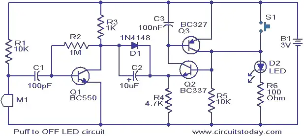
Puff to OFF LED circuit.


Descrption.
This is a simple circuit in which the glowing LED can be switched OFF just by a puff. A condenser mic (M1) is used to sense your puff. When the push button S1 is pressed, the transistors Q2 and Q3 wired as latching pair gets activated and drives the LED to glow. The LED remains in this condition. When you puff on the condenser mic, the sound pressure is converted into a voltage signal at its output. This voltage signal will be amplified by the transistor Q1.Since the collector of the Q1 is coupled to the emitter of the latching pair, the pair will stop conducting when ever there is a signal from the condenser mic due to puffing and the LED will go OFF.  The push button switch S1 has to be pressed again to switch the LED ON.
Circuit diagram with Parts list.
puff-top-off-led.JPG
Notes.
  • The circuit can be powered from a 3V battery.
  • The M1 can be a general purpose condenser microphone.
  • The switch S1 can be push button switch.
  • The circuit can be assembled on a good quality PCB or common board.
  • Instead of the LED, you can also try a low power 3V bulb

Automatic headlight dim switch.


Description.
With this cool circuit integrated to your cars headlight system , you can drive cool headed in high beam.The circuit will take over the duty of low beaming the headlight when vehicles approach against , and high beams the lights when they pass over.
The circuit is based on a photo transistor(Q1) for sensing the approaching vehicles and transistor Q2 (BC177) for switching the relays for controlling the headlight.When the light from the opposite vehicle falls on Q2 , it’s collector current increases and turns ON Q1.The relay will be activated and the head light will be dimmed.When the vehicle pass over the reverse will happen.
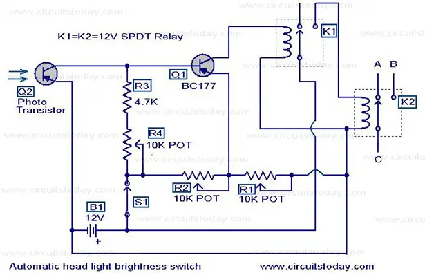
Circuit diagram with Parts list.
automatic-headlight-dim-switch.jpg
Notes.
  • The battery B1 can be the 12V car battery itself.
  • Adjust POT’s R1,R2,R4 to obtain optimum performance.
  • The Q1 can be any general purpose PNP photo transistor.It should be mounted in front of the car so that the light from opposite vehicle easily falls on it.
  • Relay contact A goes to high beam circuit,B to low beam circuit and C is the common point.
  • Carefully understand the wiring of your car before attempting to install the circuit.Wrong connections could easily bring trouble to your cars wiring

Page Rank

google pagerank

Write For Us

Submit a Guest Post

Find us on Facebook

Categories

555 Timer IC 7 segment Display 8051 Project AC Circuits Adafruit Alarms Amplifier Circuits Analog Circuits android Arduino arm processor Assembly Languange Atmel Atom Size Audio Circuits augmented reality Automotive Circuits avr Battery Circuits Bicycle Gurad bluetooth Cable TV Circuits Cambridge University Camera Technology Circuit Boards Clipping And Clamping Circuits Clocking And Timer Circuits Computing contact lens Contact Us Form Contests Controller Circuit Conversion Circuits Counter Circuits Digital Electronics diy circuits Downloads EFY EFYTimes Electronic Books Electronic Components Electronic Locks And Keys Engineering Fan Circuits Filter Circuits Fire Alarm free Frequency Fun And Game Circuits future Google Hack n Mod Ham Radio Circuits heart rate monitoring High Voltage Circuits Home Circuits IC Guide ieee Industrial Circuits Infrared Instructables Inventions ipad lcd Led Circuits Light Related Lighting Circuits Medical Circuits Meter Clocks Microcontrollers Microprocessors Mini Projects modules Movie maker NatGeo Navigation Notice Optical Fiber PC Circuits PCB Boards Physics pnp transistor Power Supplies Printing Projects Programmer Project Ideas Projectors Protection circuits Proximity Detectors Radar Radio Circuits Radio Transmitters Raspberry Raspberry Pie Remote Circuits Retis Lab RFID Robot Cars Robotics Science Science Alert Security And Safety Sensor Circuits Servo Motors Smallest Smartwatches sms Software solar cell sound application Spectram Switch Technology News Telephone Related Television Related Test And Measurement Circuits Thermal Projects Tone generator circuits Touch Screen Tutorials Wearables Wi-Fi Wireless
Like us on Facebook
Follow us on Twitter
Recommend us on Google Plus
Subscribe me on RSS