Search This Blog

Powered by Blogger.

Translate

Home » » Mini UPS

Mini UPS


Here the simple Mini UPS circuit diagram. This circuit can provide an uninterrupted power supply (UPS) to operate 12V, 9V and 5V DC-powered instruments at up to 1A current. The backup battery will take up the load with no spikes or delay when the mains electrical power gets interrupted. It could possibly also be utilized as a workbench power supply that delivers 12V, 9V and 5V operating voltages. The circuit instantly disconnects the load when the battery voltage decreases to 10.5V to avoid deep discharge of your battery. LED1 indication is presented to indicate the complete charge voltage level of the battery. Miniature white LEDs (LED2 and LED3) are utilized as emergency lamps especially during electrical power failure at night time.
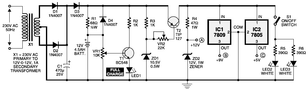
A common step-down transformer delivers 12V of AC, that is rectified by diodes D1 and D2. Capacitor C1 features ripple-free DC to charge the battery and to the remaining circuit. When the mains electrical power is on, diode D3 gets forward biased to charge the battery. Resistor R1 limits the charging current. Potentiometer VR1 (10k) with transistor T1 acts as being the voltage comparator to indicate the voltage level. VR1 is so adjusted that LED1 is in the ‘off’ mode. when the battery is completely charged, LED1 glows indicating a maximum voltage level of 12V.
Download the circuit diagram of Mini UPS and full explanation about how it’s work, download this PDF file:
» Download Link
Share this on your favourite network

2 comments:

  1. This is a fascinating article. As I am interested in designing a UPS that is also a power supply (DC), this looks like it will help me on my way.

    My only question is... we use 120V AC, not 220V AC. Is the only change necessary, the type of transformer? Can I get one at Radio Shack or similar?

    ReplyDelete
  2. you can use 120v -> 240v converter...

    u can buy it here http://goo.gl/ToQXcb $22 only

    ReplyDelete

Page Rank

google pagerank

Write For Us

Submit a Guest Post

Find us on Facebook

Categories

555 Timer IC 7 segment Display 8051 Project AC Circuits Adafruit Alarms Amplifier Circuits Analog Circuits android Arduino arm processor Assembly Languange Atmel Atom Size Audio Circuits augmented reality Automotive Circuits avr Battery Circuits Bicycle Gurad bluetooth Cable TV Circuits Cambridge University Camera Technology Circuit Boards Clipping And Clamping Circuits Clocking And Timer Circuits Computing contact lens Contact Us Form Contests Controller Circuit Conversion Circuits Counter Circuits Digital Electronics diy circuits Downloads EFY EFYTimes Electronic Books Electronic Components Electronic Locks And Keys Engineering Fan Circuits Filter Circuits Fire Alarm free Frequency Fun And Game Circuits future Google Hack n Mod Ham Radio Circuits heart rate monitoring High Voltage Circuits Home Circuits IC Guide ieee Industrial Circuits Infrared Instructables Inventions ipad lcd Led Circuits Light Related Lighting Circuits Medical Circuits Meter Clocks Microcontrollers Microprocessors Mini Projects modules Movie maker NatGeo Navigation Notice Optical Fiber PC Circuits PCB Boards Physics pnp transistor Power Supplies Printing Projects Programmer Project Ideas Projectors Protection circuits Proximity Detectors Radar Radio Circuits Radio Transmitters Raspberry Raspberry Pie Remote Circuits Retis Lab RFID Robot Cars Robotics Science Science Alert Security And Safety Sensor Circuits Servo Motors Smallest Smartwatches sms Software solar cell sound application Spectram Switch Technology News Telephone Related Television Related Test And Measurement Circuits Thermal Projects Tone generator circuits Touch Screen Tutorials Wearables Wi-Fi Wireless
Like us on Facebook
Follow us on Twitter
Recommend us on Google Plus
Subscribe me on RSS