Search This Blog

Powered by Blogger.

Translate

Jet engine sound generator

Description.

This jet engine sound generator circuit is based on the sound generator IC HT2844P from Holtek Semiconductors. This particular IC can make four sounds namely low speed sound of jet engine, high speed sound of jet engine, missile sound and machine gun sound. Each of these sounds can be activated by connecting the pins 12, 13, 14and 15 to ground by using the respective push button switches. Resistor R3 can be used for manually increasing or decreasing the speed.LED D1 gives a visible indication of the sound.
Circuit diagram.
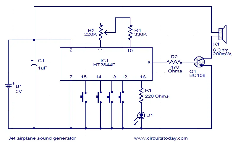
jet-engine-sound-generator
Notes.
  • The circuit can be powered from a 3V battery.
  • Do not give more than 3.3V to the IC.
  • K1 can be a 200mW/8 Ohm speaker.
  • IC1 must be mounted on a holder.

Door bell circuit using NE555


Description.
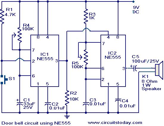
The main part of this doorbell circuit are two NE555 timer ICs.When some one presses switch S1 momentarily ,the loud speaker sounds a bell tone as long as the time period of the monostable multivibrator built around IC1.
When the switch S1 pressed, IC1 is triggered at its pin 2 and output pin 3 goes high for a time period previously set by the values of POT R4 and POT R5.When the output ofIC1 goes high it resets IC2 and it starts to oscillate to make a bell sound through the speaker.The IC2 is configured as an astable multivibrator whose oscillation frequency can be varied with the help of POT R5.By adjusting the values of R4 & R5, modifications on the tone are possible.
Circuit diagram with Parts list.

door-bell-circuit-using-ne555.JPG
Notes.
  • The circuit has to assembled on a good quality PCB or common board.
  • The IC1 & IC2 has to be mounted on IC holders.
  • Power the circuit from a 9V battery or 9V DC power supply.
  • Switch S1 is push button switch

UJT Organ circuit


Description.
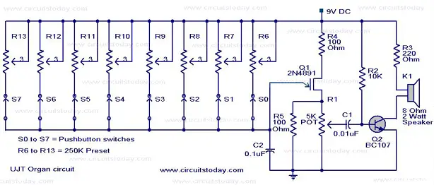
Here is the circuit diagram of a simple yet interesting mini organ based on UJT 2N 4891( Q1).You can produce the desired sound by pressing each pushbuttons.You have also the option to set each push button to produce the desired tune you want.
The circuit is based on a UJT oscillator who’s frequency is determined by the Presets R6 to R13(one at a time) and capacitor C2.The transistor Q2 drives the speaker to produce reasonable sound output.For each pushbutton press the corresponding preset will be added to the circuit ,and the UJT oscillates in a frequency proportional to it.This frequency will be amplified by the transistor to produce the sound at the speakers.A 9V battery or 9V DC power supply can be used to power the circuit.
Circuit diagram with Parts list.
organ-circuit.jpg
Notes.
  • Power up the circuit and adjust the presets (R6 to R 13) to get the desired tune at the  output for the press of corresponding push button.
  • Preset R1 (5K)  can be used as a volume control.
  • You can also try different values for C2 get the desired tunes.
  • All capacitors are of ceramic type

Canary chirp generator


Description.
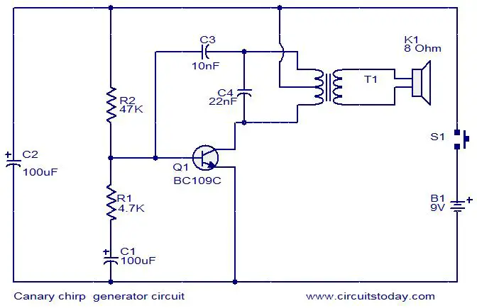
This is a simple electronic alarm circuit that imitates the chirping of a canary. The circuit is nothing but a Hartley oscillator with few more passive components added. As the capacitor C1 charges through the resistor R1 and the transistor Q1 is driven to cut off. This makes the oscillations to stop. As the capacitor discharges through the Resistor R1 and base emitter junction of the transistor the oscillation start again. Actually the R1 and C1 are the components that make the characteristic chirping sound.
Circuit diagram with Parts list.
canary-chirping-generator-circuit
Notes.
  • Assemble the circuit on a general purpose PCB.
  • The circuit can be powered from a 9V PP3 battery.
  • The transformer T1 can be a audio output transformer like LT700.
  • If LT700 is not available, try the audio output transformer used on you old transistor radio board.
  • The speaker can be an 8 ohm tweeter.
  • Switch S1 can be a push button switch.
  • The chirping sound can be altered by changing the value of R1 and C1

Whistle to beep circuit


Description.
This simple circuit produces a beeping sound that lasts for around 3 seconds whenever you make a whistle. The CMOS Hex inverter CD4049 is the heart of this circuit. Out of the six inverters in CD4049, U1a is wired as an audio amplifier which amplifies the signal picked up by the microphone M1.The U1b is wired as a band pass filter with center frequency around 2KHz.The filter is necessary in order to pass the frequency corresponding to whistling sound and suppress all other frequencies .If the filter is not there, the circuit could easily get false triggered.U1d is wired as a 3S delay monostable multivibrator.The output U1d drives the astable multivibrator formed by U1e and U1f.The astable multivibrator is operating around 4Hz.The combined effect is a intermittent beeping sound that lasts for around 3S.Transistor Q1 is used to drive the buzzer B1.
Circuit diagram with Parts list.
whisle-to-beep-circuit
Notes.
  • Assemble the circuit on a good quality PCB.
  • The circuit can be powered from a 3V battery.
  • IC U1 is a CMOS CD4049 Hex inverter.
  • M1 can be an electret microphone.
  • B1 can be a 3V piezo buzzer.
  • Mount the IC on a holder.
  • The duration of beeping can be adjusted by varying the components C4 and R9

Police siren using NE555

Description.

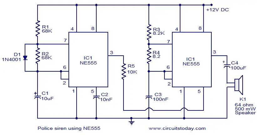
A lot of electronic circuits using NE555 timer IC are already published here and this is just another one.Here is the circuit diagram of a police siren based on NE55 timer IC. The circuit uses two NE555 timers ICs and each of them are wired as astable multivibrators.The circuit can be powered from anything between 6 to 15V DC and is fairly loud.By connecting an additional power amplifier at the output you can further increase the loudness.

IC1 is wired as a slow astable multivibrator operating at around 20Hz @ 50% duty cycle and IC2 is wired as fast astable multivibrator operating at around 600Hz.The output of first astable mutivibrator is connected to the control voltage input (pin5) of IC2. This makes the output of IC2 modulated by the output frequency of IC1, giving a siren effect. In simple words, the output frequency of IC2 is controlled by the output of IC1.

Circuit diagram.
police-siren-using-NE555

Notes.
  • The circuit can be assembled on a Perf board.
  • I used 12V DC for powering the circuit.
  • Instead of using two NE55 timer ICs, you can also use a single NE556 timer.
  • NE556 is nothing but two NE555 ICs in one package.
  • Refer the datasheets of NE555 and NE556 to have a clear idea.
  • Speaker can be a 64ohm, 500mW one.

Page Rank

google pagerank

Write For Us

Submit a Guest Post

Find us on Facebook

Categories

555 Timer IC 7 segment Display 8051 Project AC Circuits Adafruit Alarms Amplifier Circuits Analog Circuits android Arduino arm processor Assembly Languange Atmel Atom Size Audio Circuits augmented reality Automotive Circuits avr Battery Circuits Bicycle Gurad bluetooth Cable TV Circuits Cambridge University Camera Technology Circuit Boards Clipping And Clamping Circuits Clocking And Timer Circuits Computing contact lens Contact Us Form Contests Controller Circuit Conversion Circuits Counter Circuits Digital Electronics diy circuits Downloads EFY EFYTimes Electronic Books Electronic Components Electronic Locks And Keys Engineering Fan Circuits Filter Circuits Fire Alarm free Frequency Fun And Game Circuits future Google Hack n Mod Ham Radio Circuits heart rate monitoring High Voltage Circuits Home Circuits IC Guide ieee Industrial Circuits Infrared Instructables Inventions ipad lcd Led Circuits Light Related Lighting Circuits Medical Circuits Meter Clocks Microcontrollers Microprocessors Mini Projects modules Movie maker NatGeo Navigation Notice Optical Fiber PC Circuits PCB Boards Physics pnp transistor Power Supplies Printing Projects Programmer Project Ideas Projectors Protection circuits Proximity Detectors Radar Radio Circuits Radio Transmitters Raspberry Raspberry Pie Remote Circuits Retis Lab RFID Robot Cars Robotics Science Science Alert Security And Safety Sensor Circuits Servo Motors Smallest Smartwatches sms Software solar cell sound application Spectram Switch Technology News Telephone Related Television Related Test And Measurement Circuits Thermal Projects Tone generator circuits Touch Screen Tutorials Wearables Wi-Fi Wireless
Like us on Facebook
Follow us on Twitter
Recommend us on Google Plus
Subscribe me on RSS