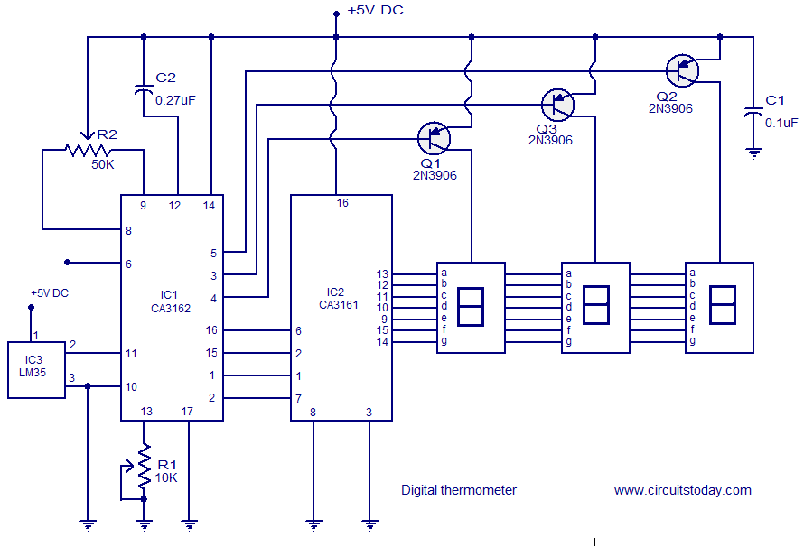
Digital thermometer circuit.
CA3162, CA3161 & LM35.
A simple digital thermometer circuit with out a micro controller and having a seven segment LED read out is shown here. The circuit is based on three ICs: CA3162, CA3161 and LM35. CA3162 is a monolithic analogue to digital (A/D) converter that has BCD output. The A/D converter inside the IC is a dual slope type with differential inputs. The IC has an internal timing circuitry and hold function. When the hold function is enables, the output IC latches itself to the present state. CA3161 is a monolithic BCD to seven segment converter IC. It can directly drive a seven segment display and there is no need for current limiting resistors. LM35 is a three terminal precision temperature sensor IC from National semiconductors. The output of LM35 is highly linear and has a scale factor of 10mV/C. The IC consumes only 60uA as standby current and is calibrated directly in degree Celsius.
Circuit diagram.

Digital thermometer circuit
About the circuit .
IC LM35 is used for sensing the temperatures. A voltage proportional to the temperature will be available at pin 2 of the LM35 and this voltage is coupled to the high input pin (pin11) of the CA3162. CA3162 does the job of converting this analogue voltage in to a BCD format. POT R1 connected at pin 13 of the CA3162 is used for gain adjustment while POT R2 can be used for ZERO adjustment. Capacitor C2 is the integrating capacitor of the A/D converter circuitry inside the IC. The working of the CA3162 is as follows, the voltage applied to the input pin (pin11) is converted into a current (using the built in V/I converter circuit) that charges the integrating capacitor C2 for a preset amount of them. Then the integrating is disconnected from the V/I converter circuit and a reference constant current source is connected to the integrating capacitor. The time taken for the charge to restore to its original value is noted and the number of clock cycles elapsed during this time will be a measure of the charge induced by the input voltage (voltage applied to pin 11). The point of restoration is sensed using an internal comparator which latches the counter and the count is then multiplexed into the BCD outputs and the entire cycle is repeated. The hold pin CA3162 (pin6) can be used for running the IC in different modes. When the hold pin is grounded or left open the IC runs in low speed mode (sampling rate is 4Hz). When hold pin is held at +5V, the IC runs in high speed mode i.e. a sampling rate of 96Hz. When the hold pin is held at a fixed 1.2V, the BCD output latches to the current state. C1 is the power supply bypass capacitor whose job is to bypass noise if any from the power supply line.
The next section of the circuit is the BCD to seven segment decoder plus display driver section. For that purpose CA3161 is used. The BCD output pins of the CA3162 are connected to the input pins of the CA3161. Transistors Q1, Q2, Q3 common anode terminals of the corresponding seven segments displays. Q1, Q2, Q3 are driven by the 4, 3, 5 pins (digit driver pins) of the CA3162 respectively.
Notes.
- The circuit can be assembled on a vero board or on a PCB.
- Use 5V DC for powering the circuit.
- POT R2 can be used for Zero adjustment.
- IC2 and IC1 must be mounted on holders.
- Capacitor C1 must be placed as close as possible to the power and ground pins of the CA3162.
- Capacitor C2 could be a polyester type while C1 can be a ceramic capacitor.
- The DC power supply used for powering this circuit must be well regulated and free from any sort of noise.
- The type numbers of the driver transistor are not critical and you can make suitable substitutions.
- Hold function can be enabled by providing the pin 6 with 1.2V using a voltage divider network.
Share this on your favourite network


Thanks for sharing such a great information. Digital Thermometer
ReplyDeleteThis was really an interesting topic and I kinda agree with what you have mentioned here! cloud based digital signage
ReplyDelete