
Description.
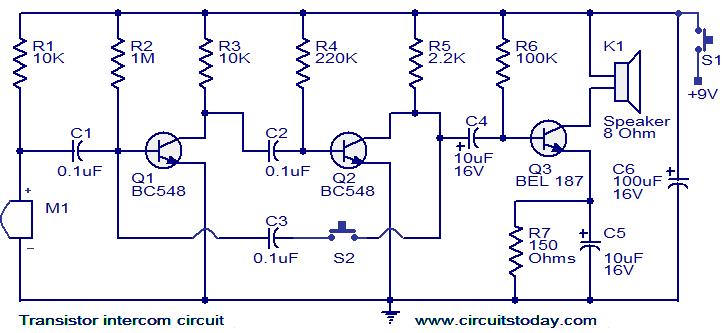
Here is a simple but effective intercom circuit that is based fully on transistors.The circuit is based on a three stage RC coupled amplifier. When the pushbutton S2 is pressed, the amplifier circuit wired around T1 & T2 becomes an astable multivibrator and starts producing the ringing signals. These ringing signals will be amplified by the transistor T3 to drive the speaker. When the push button S2 is released the circuit will behave as an ordinary amplifier and you can talk to the other side through it.
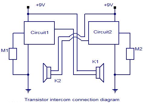
To construct a two way intercom, make two identical copies of the circuit given below and connect it according to the given connection diagram. The stand by current consumption of this circuit is around 20mA.
Circuit diagram with Parts list.
Connection diagram.
Notes.
- Assemble the circuit on a good quality PCB.
- Use 9V PP3 battery for powering the circuit.
- The Mic M1 can be condenser micro phone.
- Use push to ON type push button switch for S2.
- Use a slide switch for switch S1.S1 can be used to power the circuit
I can't find the transistor BEL187 anywhere in the market so can anyone suggest for its substitute?
ReplyDeleteany general purpose NPN amplifier will do. The 2N3904 is one example
DeleteWhere do the negative voltage source be connected?
ReplyDeleteThanks and I have a neat proposal: How To Become A House Renovation victorian house remodel
ReplyDelete