
Description.
Here is a versatile remote controlled appliance switch that can ON or OFF any appliance connected to it using a TV remote.
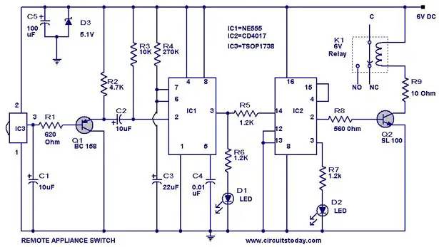
IR remote sensor IC TSOP 1738 is used for recieving the signal. Normally when no signal is falling on IC3 the output of it will be high.This makes Q1 OFF.When a signal of 38 KHz from the TV remote falls on the IC3 its output goes low.This makes Q1 conduct and a negative pulse is obtained at pin 2 of IC 1 NE 555.Due to this IC1 wired as a monostable multivibrator produces a 4 Sec long high signal at its out put.This high out put is the clock for IC 2 which is wired as a Flipflop and of , its two outputs pin 3 goes low and pin 2 goes high.The high output at pin 2 is amplified to drive the relay .For the next signal the outputs of IC2 toggles state. Result, we get a relay toggling on each press on the remote.Any appliance connected to this circuit can be switched ON or OFF.
Circuit Diagram with Parts List .
 Notes.
- Before wiring the circuit make sure that the carrier frequency of the TV remote you have is 38 KHz.For that wire the sensor part only ,point your remote to the TSOP1738 and press any switch.If out put of TSOP1738 goes low them ok, your remote is of 38Khz type.Nothing to worry almost all TV remote are of this type.
- You can use any switch because for any switch the code only changes,the carrier frequency remains same.We need this carrier frequency only.
- Assemble the circuit on a good quality PCB or common board.
- The appliance can be connected through NO or NC and contacts of the relay
No comments:
Post a Comment