
Description.
Low power ( 3 to 30 MHz) transmitters constructed by hams are generally called QRP’s. For such transmitters a well tuned antenna is a must.If the impedance is not properly matched there will be a little or no output.But if properly matched there will be great results.A circuit for matching the antenna properly with the transmitter id given below.
The output of the transmitter is given to the input of the tuner( connector BNC1). The output of the tuner(connector BNC2) must be connected to antenna.Then adjust the L1 and C1 to obtain the maximum transmission power.The transmission power can be checked using a SWR meter.
Circuit diagram with Parts list. 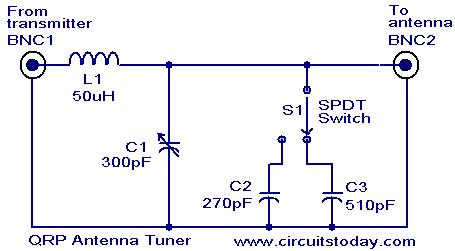
Notes.
- Assemble the circuit on a goos quality PCB or common board.
- If the matching is not satisfactory then change the values of L1,C1,C2&C3 to the next close value and tune again.
- Proper tuning requires some trial and error.
- The circuit can be enclosed in an aluminum casing for better performance
No comments:
Post a Comment