
Description.
This circuit will produce a visual as well as audible alert whenever the connection between the charger circuit and the battery being charged.What ever be the situation whether it be a loose contact or breakage the circuit will give you the alarm.Such a circuit can be very handy in the fail safe charging of the batteries in some applications , like as in burglar alarms etc.This circuit can be easily assebled from the components in your electronic junk box.
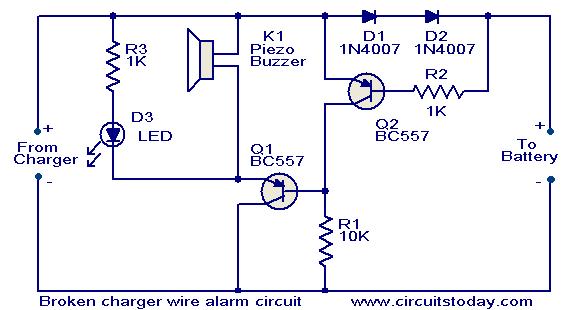
As long as there is a little current flows from the charger to battery the diodes D1 and D2 will conduct.This forward voltage drop of 1.4 V across the diodes make the Q2 ON.So the transistor Q1 will be OFF.When there is no at all any current flowing (when the wire is broken or there is a loose contact) there will not be any drop across D1&D2 and so Q2 will be OFF.This makes the Q1 ON,the buzzer beeps and the LED glows.
Circuit diagram with Parts list.
Notes.
- For this circuit to operate effectively the supply voltage must atleast 1V higher than the voltage required by the charged device.
- The circuit can operate safely in a range of 3-16 V.
- Assemble the circuit can be assembled on a good quality PCB or common board.
- The transistors are not very value specific.Any PNP transistors will do the job
No comments:
Post a Comment